Table of Contents
Advertisement
Shenzhen Growatt New Energy Technology CO.,LTD
No.28 Guangming Road, Longteng Community,
Shiyan, Bao'an District, Shenzhen, P.R.China
T
+ 86 755 2747 1942
service@ginverter.com
E
W
www.ginverter.com
GR - UM -140-A- 01
Installation
&
Operation Manual
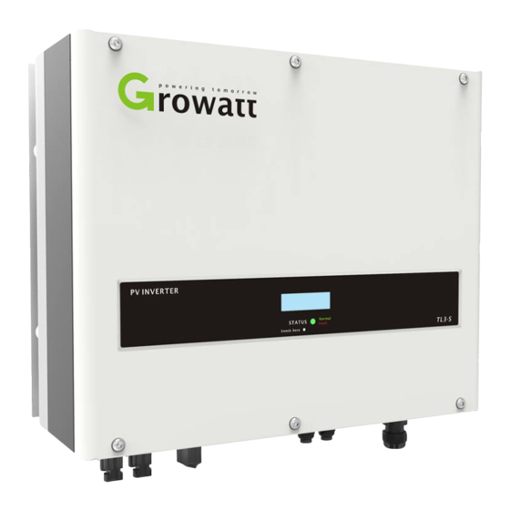
Growatt 3000TL3-S
Growatt 4000TL3-S
Growatt 5000TL3-S
Growatt 6000TL3-S
Growatt 7000TL3-S
Growatt 8000TL3-S
Growatt 9000TL3-S
Growatt 10000TL3-S
Growatt 11000TL3-S
Growatt 12000TL3
Growatt 12000TL3-S
Growatt 13000TL3-S
Growatt 15000TL3-S
Advertisement
Table of Contents
Troubleshooting


Need help?
Do you have a question about the 10000TL3-S and is the answer not in the manual?
Questions and answers