Table of Contents
Advertisement
Quick Links
Advertisement
Table of Contents

Subscribe to Our Youtube Channel
Related Manuals for Riello INSIEME EVOe 32 B/110 LN


Summary of Contents for Riello INSIEME EVOe 32 B/110 LN
- Page 1 INSIEME EVOe 32 B/110 LN EN INSTALLATION AND MAINTENANCE MANUAL...
- Page 2 Please accept our thanks and our congratulations on your choice of product. Riello S.p.A. CONFORMITY INSIEME EVOe 32 B/110 LN boilers conform to the following di- rectives: − Directive 92/42/EEC on efficiency requirements − Electromagnetic Compatibility Directive 2014/30/EU − Low Voltage Directive 2014/35/EU −...
-
Page 3: Table Of Contents
CONTENTS 1 GENERAL INFORMATION . . . . . . . . . . . . . . . . . . . . . . . . . . . . 4 2.15 Enter password. -
Page 4: General Information
If it is damaged or lost, request an- other copy from your local Technical Assistance Service The thermal unit INSIEME EVOe 32 B/110 LN is a hot water genera- This manual must be read carefully so as to ensure the cor-... -
Page 5: Safety And Control Devices
Identification The control panel, apart from managing the functions of the The products are identified by: thermal unit INSIEME EVOe 32 B/110 LN, allows to highlight any anomaly which may affect its correct operation, ensuring the Serial number plate thermal unit safety by stopping it and automatically closing the Contains the serial number, the model and the main tech- burner light oil valve. -
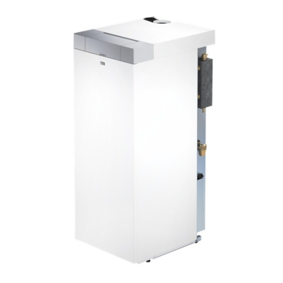
Page 6: System Layout
GENERAL INFORMATION System layout INSIEME EVOe 32 B/110 LN Electric actuator 3-way diverting valve Main switch Heating safety valve Storage cylinder expansion vessel Control panel Heating expansion reservoir Burner Boiler drain cock 10 Magnesium anode Storage cylinder inspection flange 12 Storage cylinder flange insulation... - Page 7 GENERAL INFORMATION BURNER Pump Pressure gauge fitting Burner controller Photoresistor Reset button with lockout indicator 10 Flame pipe Flange with seal Condenser Air damper adjuster screw 12 Motor Air intake 13 Heating element Oil pump pressure adjuster screw OIL PUMP Suction port Return By-pass screw...
-
Page 8: Technical Specifications
GENERAL INFORMATION Technical specifications DESCRIPTION INSIEME EVOe 32 B/110 LN Mixed low temperature Device type heating B23-C13(*)-C33(*)-C63(*) Fuel Heating fuel oil (light oil) Combustion chamber vertical Maximum rated heat input at furnace referred to HVC (LCV) 36 (33,9) Useful (rated) heat output Maximum useful heat output (80-60°C) - Page 9 GENERAL INFORMATION DESCRIPTION INSIEME EVOe 32 B/110 LN Index of protection Power supply 230 V - 50 Hz Absorbed power supply (max) Consumption at full load Elmax Consumption at part load Elmin Electrical consumption in standby mode LCV: Lower calorific value of fuel...
-
Page 10: Pump
GENERAL INFORMATION Pump DESCRIPTION INSIEME EVOe 32 B/110 LN Electrical consumption EEI Part 3 (*) ≤ 0,20 P L,Avg (**) ≤ 23 Minimum pressure at pump suction inlet (*) Energy efficiency rating according to regulations 641/2009-622/2012 (**) Approximate average annual electricity consumption according to regulations 641/2009-622/2012... -
Page 11: Location Of Sensors
GENERAL INFORMATION Location of sensors INSIEME EVOe 32 B/110 LN Delivery temperature probe Return temperature probe Safety thermostat Pressure transducer Boiler sensor Heater sensor bath... -
Page 12: Control Panel
GENERAL INFORMATION 1.10 Control panel Controls interface Door Light guide Rear light display ENTER/RESET key: it allows accessing the main menu and restoring the operation after a stop due to an anomaly Navigation keys Main switch (located on the equipment rear wall) Light Guide displaying STATUS DESCRIPTION... - Page 13 GENERAL INFORMATION Display visualisation HEAT °C °F OUTSIDE Icon displayed when heating mode is enabled. Blinking when there is a heat demand Icon displayed when DHW mode is enabled. Blinking when there is an DHW Demand Icon displayed when entering the "Installer" menu Icon displayed when the burner of the equipment is on.
-
Page 14: Installation
Unpacking the product INSIEME EVOe 32 B/110 LN The INSIEME EVOe 32 B/110 LN boiler is supplied on a pallet, pro- tected by a non-scratch cloth and a triple wall cardboard box. Check immediately that there is no damage and that the boil- er is exactly as ordered. -
Page 15: Moving And Removing The Packing
INSTALLATION Moving and removing the packing Do not dispose of packaging material into the environment, or leave it within the reach of children, since it can become a potential hazard. Dispose of packaging material in com- Wear suitable personal protection equipment when moving pliance with applicable legislation. -
Page 16: Installation Premises
− Unscrew the screws (1) securing the boiler to the pallet; − remove the fixing screw (2) and extract the front panel The thermal unit INSIEME EVOe 32 B/110 LN must be installed (3).; in rooms with appropriately sized vent openings which com- Use lifting equipment suitable for the weight involved. -
Page 17: Recommended Minimum Distances
The following table gives the dimensions and positions of the be respected in order to allow proper maintenance of the boiler. water fittings for INSIEME EVOe 32 B/110 LN boilers. Before installing the boiler, flush out all the pipes of the central heating circuit to remove any machining residues. -
Page 18: Boiler Water Circuit
INSTALLATION Boiler water circuit 2.8 Typical system schematic Typical installation schematic Disconnect valves CH radiator DHW circulation pump Non-return valve Pressure reducer Boiler body Water softener filter Automatic vent valve Safety valve drain Pump Central heating circuit and storage cylinder drains Safety valve DHW user Burner... -
Page 19: Fuel Connections
If the oil feed system is in negative pressure, the return line must reach the same height as the suction line. This avoids having to The boiler INSIEME EVOe 32 B/110 LN is supplied with two hoses install a bottom valve, which would be essential if the return for the light oil supply to the burner. -
Page 20: Discharge Of Combustion Products
INSTALLATION 2.10 Discharge of combustion products If a confirmation solenoid valve is to be installed in the light oil supply circuit to the burner, only a one-pipe system can The flue pipe (1) and the connection to the stack (2) must be be set. -
Page 21: Technical Specifications Of Stack
INSTALLATION INSIEME EVOe 32 B/110 LN boilers derive their comburent air from "OPEN" CONFIGURATION OF THE TYPE B BOILER the room in which they are installed. Suitable air vents must The equipment is supplied as standard in type B configura-... - Page 22 (This length must be reduced by 1 metre for every 90° curve and by 0.5 metres for every 45° curve.) Type C transformation accessory Description INSIEME EVOe 32 B/110 LN Concentric flue kit Flue gas vent and Condensation exhaust system (not supplied)
-
Page 23: System Filling And Emptying
INSTALLATION 2.11 System filling and emptying The thermal unit INSIEME EVOe 32 B/110 LN is equipped with an internal system load valve (1), which can be reached by remov- ing the front panel. Before performing any system filling or emptying operation, set the system main switch to OFF and the equipment main switch to (0). -
Page 24: Filling
INSTALLATION 2.11.2 Filling − To empty the boiler, connect a rubber tube (A) (in- tø=12mm) to the hose connector of the boiler drain valve Before starting, check that: (1) and open it. − The boiler drain (3) and the heater drain (2) valves are closed and that the shut-off valves on the cold water in- let (CWI) are open;... -
Page 25: Wiring Diagram
INSTALLATION 2.12 Wiring diagram P W M CNX1 CNX4 CN X9 CN 25 CN X19 CN X8 CN X21 CN X2 1 2 3 4 5 6 7 8 9101112 6 7 8 910 1 2 3 1 2 3 4 1 2 3 4 P W M R HD E... -
Page 26: Electrical Connections
2.13 Electrical connections Automatic shut-off device (not supplied) The INSIEME EVOe 32 B/110 LN boiler is fully cabled in the factory. The only connections required for its installation are those of the mains power supply, room thermostat and other optional system components. - Page 27 INSTALLATION − close the door and turn the control panel outwards; − on completion of the electrical connections, replace all removed components in the opposite order. The following is mandatory: − The use of an omnipolar magnetothermic switch, line disconnecting switch in compliance with CEI-EN stand- ards (contact opening of at least 3 mm) −...
-
Page 28: Menu Navigation
INSTALLATION 2.14 Menu navigation At start-up or when no key is pressed for more than 4 minutes, the display is in “basic display” mode and provides general infor- mation on the equipment operation. In this mode, keys have the following functions: Button Function "+"... -
Page 29: Enter Password
INSTALLATION MENU selection Access the “menu” mode by pressing the key “ENTER/RESET” The digits of the small display indicate “0000”, which is the first acces- sible menu. In this mode, keys have the following functions: Button Function "+" Exits from the menu and cancels a parameter change "-"... -
Page 30: Navigation Scheme
INSTALLATION 2.16 Navigation scheme "Basic display" mode °C "End user" mode "installer" mode Enter password Example of parameter setting change con rmed change canceled... -
Page 31: List Of Parameters
INSTALLATION 2.17 List of parameters Access level: The programming lines can be hidden, according to the access level (User, Installer) and to End user the thermal unit configuration. Installer The parameters of Installer level must be changed only by the Technical Assistance Service Key: OpenTherm DHW Domestic hot water... - Page 32 INSTALLATION Default setting Par. Menu Description Range INSIEME EVOe 32 cess B/110 LN 1000 1056 Total hours of operation in heating mode h x 10 1000 1057 Total hours of operation in domestic mode h x 10 1000 1058 Total hours of operation h x 10 1000 1063 Input signal 0-10V...
- Page 33 INSTALLATION Default setting Par. Menu Description Range INSIEME EVOe 32 cess B/110 LN If Zone 1 is not ena- Direct Zone/Zone 1 heating setpoint at the minimum bled: external temperature (Par. 2121, Par. 2024) 82 (AT) 2000 2119 The range of this parameter is limited by the values °C If Zone 1 is enabled: 45 (BT)
- Page 34 INSTALLATION Default setting Par. Menu Description Range INSIEME EVOe 32 cess B/110 LN Zone 2 minimum heating setpoint at basic external temperature (Par. 2222) 30 (AT) BT: (20, Par. 2219) 2000 2221 It sets the minimum heating setpoint when the °C AT: (Par.
- Page 35 INSTALLATION Default setting Par. Menu Description Range INSIEME EVOe 32 cess B/110 LN Zone 3 basic external temperature It sets the external temperature at which the boiler 2000 2322 5...30 °C setpoint must be reduced, according to the value de- fined in parameter 2321.
- Page 36 INSTALLATION Default setting Par. Menu Description Range INSIEME EVOe 32 cess B/110 LN 2063 ∆T boiler delivery / boiler return 2000 5...40 °C Burner anti-freeze protection 2000 2074 0 = NO 0…1 1 = Yes Heating circuit anti-freeze protection 2000 2075 0 = NO 0…1...
-
Page 37: Commissioning And Maintenance
COMMISSIONING AND MAINTENANCE 3 COMMISSIONING AND MAINTENANCE Firmware version of the thermal unit interface. In the example the message indicates a firmware version = 0. Preparing for initial startup The first start-up of the thermal unit must be carried out by the Technical Assistance Service. -
Page 38: Adjustment Of Heating Setpoint
COMMISSIONING AND MAINTENANCE Once the initialization phase is complete, the display switches to − To save the modification made and go back to the initial “basic display” mode. screen, wait for 3 seconds or press the key “ENTER/RESET”. In this mode, the main information on the equipment opera- −... -
Page 39: Enable/Disable The Heating Function
COMMISSIONING AND MAINTENANCE 3.2.5 Enable/disable the heating function The parameters regulating such temperature are: Par. Description − Press the keys “+” and “-” simultaneously for a few sec- onds; Main Zone/Zone 1 setpoint in heating mode Par. 2001 − The icon and the current heating mode (ON or OFF) will = 0 and 3. - Page 40 COMMISSIONING AND MAINTENANCE The heating delivery temperature is defined by a setpoint which Parameter 2131 (installer level) varies according to the external temperature and the ambient In-between seasons when the external temperature gets closer temperature on the basis of a climatic curve defined by the fol- to the maximum limit set in Par.
- Page 41 COMMISSIONING AND MAINTENANCE Parameter 2130 (user level) The equipment works with a variable setpoint defined by the The parallel shift of the climatic curve is used to modify, in a climatic curve (which can be set as described in mode 1) accord- uniform way, the delivery temperature for the whole scale of the ing to the external temperature.
-
Page 42: Setting The Domestic Hot Water Parameters
COMMISSIONING AND MAINTENANCE Mode 3: continuous operation with fixed setpoint and night re- The parameters regulating such temperature are: duction with ambient thermostat (AT) Par. Description In this mode: It limits the minimum value that can be assigned to − External probe is not required. 2023 the setpoint in heating mode. -
Page 43: Heat Request Priority
COMMISSIONING AND MAINTENANCE 3.2.8 Heat request priority Venting (Par. 2090) The function is automatically enabled at the first start-up and at Priority setting each reset of the power supply. The parameter 2042 defines the priority between domestic and When the function is active, the message “Air” is displayed. During the venting, the circulator is enabled, so that the air heating circuit. -
Page 44: Ignition Failure
COMMISSIONING AND MAINTENANCE 3.2.10 Ignition failure Warnings The text “AttE” is displayed together with the alert number. If an ignition or operating anomaly occurs, the thermal unit dis- The equipment is not locked out, but its functions may be limit- play will show a text message (small digit) and a number (large ed (according to the alert). -
Page 45: Burner Control And Adjustment
Once the analysis of the combustion products is complete, dis- able the function (Par. 200 = 0). INSIEME EVOe 32 B/110 LN (*) Adjusting pump pressure 14,5 bar ≥5°... -
Page 46: Burner Functioning And Programming
COMMISSIONING AND MAINTENANCE 3.3.2 Burner functioning and programming DESCRIPTION VALUE Standby: the burner waits for a heat request Normal functioning Standby time for an input signal: reaction time, control box remains in waiting mode ≤ 1 sec for t1 Initialisation verification time: time follow- POWER SUPPLY 3,5 sec ing startup of main power supply... - Page 47 COMMISSIONING AND MAINTENANCE Lockout caused by ignition failure DESCRIPTION VALUE Standby: the burner waits for a heat request Standby time for an input signal: reaction time, control box remains in waiting mode ≤ 1 sec POWER SUPPLY for t1 Initialisation verification time: time follow- 3,5 sec ing startup of main power supply Checks extraneous light or parasite flame...
- Page 48 COMMISSIONING AND MAINTENANCE Functioning status display Reset button Seconds Functioning status Reset button LED colour Flash time Pre-ventilation Slow Flashing ORANGE Safety time Slow Flashing GREEN Normal functioning position Steady ON GREEN Extraneous light or false flame signal Slow GREEN, RED alternate flashing Power supply frequency error Steady ON ORANGE...
- Page 49 COMMISSIONING AND MAINTENANCE MAIN BURNER FUNCTIONS POST-PURGING Heating function always on The post-purging function keeps the fan running for a set time The burner is equipped with heating function always on. In case after the burner shuts down provided there is no new heat re- of a heat request, it starts immediately with the start-up se- quest.
- Page 50 COMMISSIONING AND MAINTENANCE Menu access block diagram BURNER STATE NORMAL FUNCTIONING (FLAME LIT) AND STANDBY TYPE OF SHUTDOWN TEST POST-PURGING CONTROLLED LAST LOCKOUT FUNCTION SHUTDOWN IN MEMORY AND RESTART BUTTON 25 SECS. 5 SECS. 10 SECS. 20 SECS. RELEASE TIME NUMBER OF 2 RED 1 GREEN...
- Page 51 COMMISSIONING AND MAINTENANCE CONTROLLED SHUTDOWN AND RESTART SHUTDOWN TEST Enabling/disabling sequence: If the reset button is pressed and held down for a time between − programming permitted in NORMAL FUNCTIONING and 5 and 10 seconds during normal functioning, the burner shuts STANDBY mode;...
- Page 52 COMMISSIONING AND MAINTENANCE EXTRANEOUS LIGHT OR FALSE FLAME SIGNAL FAN MOTOR CONTROL The presence of the parasite flame or the extraneous light can be The burner controller automatically detects the presence of the detected in the standby condition when the burner is stopped fan motor and enters lockout in the event of a fan motor failure.
-
Page 53: Error List
COMMISSIONING AND MAINTENANCE 3.4.2 Temporary Errors EEPROM CONTROL The burner controller automatically checks for errors in the mi- Message Error No. Description crocontroller EEPROM and enters lockout if an error is detect- Pressure decreasing alarm (<0.8) ed. An error is indicated by the LED flashing (see the “Fault diag- E046 (temporary) nosis - lockouts”... -
Page 54: Temporary Or Short-Term Shut-Down
COMMISSIONING AND MAINTENANCE Temporary or short-term shut-down Perform the following operations before beginning any mainte- nance or cleaning: In the event of temporary or short-term shut-down (e.g. due to − set the main switch of the system to OFF and the main holidays), proceed as follows: switch of the equipment to (0);... - Page 55 − Pull the burner (3) out, taking care not to damage it; sure that it is smooth, free from deposits, burns and dents. Reverse the above steps to reassemble. REPLACING THE NOZZLE INSIEME EVOe 32 B/110 LN (*) Nozzle type 0.65 80°HF Fluidics (*) Burner with oil heater Remove the blast tube then proceed as follows: −...
-
Page 56: Boiler Exchanger Cleaning
COMMISSIONING AND MAINTENANCE − Make sure that the new nozzle is exactly the same type CLEANING THE FAN and size as the old one − Clean the contact and sealing surfaces Clean the inside and the rotor blades of the fan unit to re- −... - Page 57 COMMISSIONING AND MAINTENANCE − Remove the burner; − remove the turbulators (7) and check them for wear and − Remove the top panel (3); fin angle (replace as necessary); − remove the insulating cover (4); − use a flue brush (8) or other suitable tool; −...
-
Page 58: Checking And Replacing The Storage Cylinder Anode
COMMISSIONING AND MAINTENANCE 3.8.3 Checking and replacing the storage − clean the internal surfaces and remove any residues cylinder anode through the opening; − check the magnesium anode wear status (4) (replace it if necessary); To check the magnesium anode and its wear status: −... -
Page 59: Troubleshooting
COMMISSIONING AND MAINTENANCE 3.11 Troubleshooting FAULT CAUSE SOLUTION − Check that the burner body is clean − Check that the flue pipes are clean There is a smell of fumes Fumes escaping into the air − Check the condition of the boiler seals −... -
Page 60: Recycling And Disposal
RECYCLING AND DISPOSAL TROUBLESHOOTING Problem Diagnostic signal Probable cause Remedy Check voltage at L, N and in power plug Check the condition of No electrical power the fuses Check that the safety thermostat has not tripped The burner does not ignite when heat is requested The flame detector reads Eliminate cause of light or... - Page 64 RIELLO S.p.A. Via Ing. Pilade Riello, 7 37045 - Legnago (VR) www.riello.com The manufacturer strives to continuously improve all products. Appearance, dimensions, technical specifications, standard equipment and accessories are therefore liable to modification without notice.
Need help?
Do you have a question about the INSIEME EVOe 32 B/110 LN and is the answer not in the manual?
Questions and answers