Table of Contents
Advertisement
Quick Links
Advertisement
Table of Contents

Subscribe to Our Youtube Channel
Related Manuals for Riello INSIEME EVO 32 BS/100 LN


Summary of Contents for Riello INSIEME EVO 32 BS/100 LN
- Page 1 INSIEME EVO 32 BS/100 LN EN INSTALLATION AND MAINTENANCE MANUAL...
- Page 2 Please accept our thanks and our congratulations on your choice of product. Riello S.p.A. CONFORMITY INSIEME EVO 32 BS/100 LN boilers conform to the following di- rectives: − Directive 92/42/EEC on efficiency requirements − Electromagnetic Compatibility Directive 2014/30/EU − Low Voltage Directive 2014/35/EU −...
-
Page 3: Table Of Contents
CONTENTS 1 GENERAL INFORMATION . . . . . . . . . . . . . . . . . . . . . . . . . . . . 4 General Safety Information . -
Page 4: General Information
GENERAL INFORMATION GENERAL INFORMATION Precautions The operation of any appliance that uses fuel, electrical power General Safety Information and water demands that a number of fundamental safety pre- cautions be respected: Check that the product is complete, undamaged and as or- Do not allow children or infirm persons to operate the sys- dered as soon as you receive it. -
Page 5: Description Of The Appliance
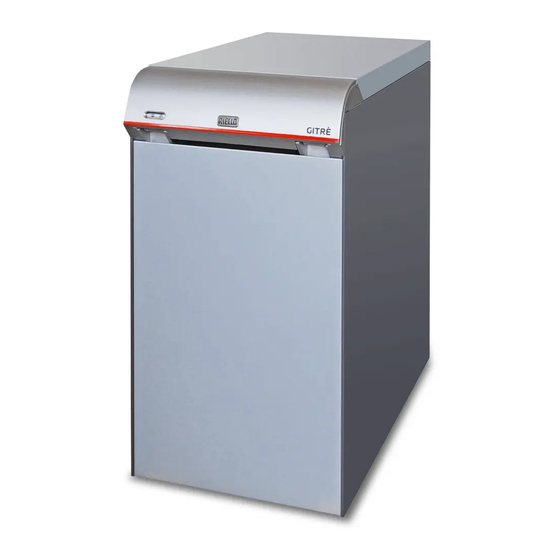
GENERAL INFORMATION Description of the appliance Identification The INSIEME EVO 32 BS/100 LN boiler produces hot water for cen- The products are identified by: tral heating and also produces domestic hot water in an inte- grated 95 litre storage cylinder. -
Page 6: System Layout
GENERAL INFORMATION System layout Fuel oil filter Control panel Boiler sensor socket Central heating circuit expansion vessel Capillary pressure gauge fitting Distribution manifold Central heating circuit safety valve Boiler drain cock Storage cylinder fill cock 10 Storage cylinder expansion vessel Storage cylinder inspection flange 12 Storage cylinder flange insulation 13 Central heating circuit pump... - Page 7 GENERAL INFORMATION BURNER Pump Burner controller Reset button with lockout indicator Flange with seal Air damper adjuster screw Oil pump pressure adjuster screw Pressure gauge fitting Photoresistor Combustion head 10 Motor Air intake OIL PUMP Suction port Return By-pass screw Pressure gauge fitting Pressure adjuster screw Vacuum gauge fitting...
-
Page 8: Technical Specifications
GENERAL INFORMATION Technical specifications INSIEME EVO 32 DESCRIPTION BS/100 LN Mixed low temper- ature heating Device type Heating fuel oil Fuel (light oil) Rated heat input at furnace referred to HVC (LCV) 35,4 (33,4) Useful (rated) heat output Maximum useful heat output (60-80°C) 31,7 30% heat output... -
Page 9: Central Heating System Pump
GENERAL INFORMATION STORAGE CYLINDER CHARACTERISTICS INSIEME EVO 32 BS/100 LN Type of storage cylinder Vitrified Storage cylinder layout Horizontal Heat exchanger layout Horizontal Maximum power absorbed 28,5 DHW temperature setting range 0-70°C °C Storage cylinder capacity Coil water capacity Heat exchange surface area 0,98 Domestic hot water production with ∆T 35°C (*) - Page 10 GENERAL INFORMATION PUMP CURVES [kPa] Q [m³/h] Flow-rate Q [l/s] Q [m³/h] The curves refer to a water density of 983.2 Kg/m , a water temperature of +20°C, and a kinematic viscosity of 0.474 mm /s (0.474 cSt).
-
Page 11: Location Of Sensors
GENERAL INFORMATION Location of sensors TR Boiler thermostat sensor Tm Minimum temperature thermostat sensor TS Safety thermostat sensor Maximum temperature thermostat sensor Boiler temperature gauge Storage cylinder temperature gauge Storage cylinder thermostat sensor Boiler temperature gauge socket... -
Page 12: Control Panel
GENERAL INFORMATION 1.10 Control panel 40 60 80 Function selector Remote burner reset Boiler temperature gauge Displays the temperature of the central heating water Boiler pressure gauge Displays the pressure in the central heating circuit Boiler thermostat Allows you to set the temperature of the central heating water (setting range 55-82°C) Electrical power indicator (green) Lights to show that the boiler is receiving electrical power Burner lockout indicator (red) -
Page 13: Installation
Overall dimensions and weights Unpacking the product The INSIEME EVO 32 BS/100 LN boiler is supplied on a pallet, pro- tected by a non-scratch cloth and a triple wall cardboard box. The following items are delivered in a plastic bag (1) inside the boiler: −... -
Page 14: Moving And Removing The Packing
INSTALLATION Moving and removing the packing Do not dispose of packaging material into the environment, or leave it within the reach of children, since it can become a potential hazard. Dispose of packaging material in com- Wear suitable personal protection equipment when moving pliance with applicable legislation. -
Page 15: Installation Premises
INSTALLATION Installation premises To move the boiler manually, proceed as follows: − Unscrew the screws (1) securing the boiler to the pallet; − Remove the front panel (2); Thanks to their sealed combustion chambers, INSIEME EVO 32 BS/100 LN can be installed in any indoor location provided the flue gases vent pipe and comburent air pipe are connected to the outdoors. -
Page 16: Recommended Minimum Distances
− Make sure that a suitable water treatment system is in- stalled if the quality of the supply/recirculation water so demands. (Refer to the reference values on page 22); See Riello S.p.A.’s Catalogue The manufacturer declines all responsibility for damage caused by incorrectly constructed flue systems. -
Page 17: Water Connections
Water connections Boiler water circuit The following table gives the dimensions and positions of the water fittings for INSIEME EVO 32 BS/100 LN boilers. CENTRAL HEATING FLOW Before installing the boiler, flush out all the pipes of the central heating circuit to remove any machining residues. -
Page 18: Typical Water System Schematics
INSTALLATION 2.8 Typical water system schematics Fuel connections Typical installation schematic The fuel oil supply pipe must be connected directly to the filter (1) and the return pipe to the fitting (2). Make sure that these connections are oil tight. Disconnect valves CH radiator DHW circulation pump... - Page 19 INSTALLATION Priming the pump To prime the oil pump simply start up the burner and check for a flame. If the burner enters lockout before any fuel reaches it, wait at least 20 seconds then turn the function selector to position (II) "Reset burner"...
-
Page 20: Flue Gas Vent And Comburent Air Intake
≥5° Øe 80 Øi 120 INSIEME EVO 32 BS/100 LN boilers are designed to function with comburent air drawn from outdoors. If comburent air is drawn from outdoors, the appliances are type C "sealed" and the boiler room does not require air vents. -
Page 21: Technical Specifications Of Stack
INSTALLATION 2.10.1 Technical specifications of stack The stack must satisfy the following requirements:: − It must be constructed from materials that are imper- meable to flue gases and that offer lasting resistance to mechanical stress, heat and the action of the products of combustion and condensate −... -
Page 22: System Filling And Emptying
2.11 System filling and emptying 2.11.2 Filling The INSIEME EVO 32 BS/100 LN boiler is fitted with a filling cock (1). − Make sure that the boiler drain cock (2) and storage cyl- inder drain cock (3) are closed before you start filling the system. -
Page 23: Emptying
INSTALLATION 2.11.3 Emptying Before draining the boiler or storage cylinder: − Turn the mains power switch OFF and turn the control panel function selector to (0). − Close the water supply shut-off cocks; − To empty the boiler, connect a rubber hose (Øint=12mm) to the hose union on the boiler drain cock (1) or storage cylinder drain cock (2), then open the cock. -
Page 24: Wiring Diagram
INSTALLATION 2.12 Wiring diagram INSIEME EVO 32 BS/100 LN WITH BURNER WITH PRE-HEATER COM.G. COM E/I DEV_ROT-2P 88YC 81YC SPT96 01 PEPB L1PB PEPI L1PI AE 230V ~ 50Hz Power supply COM.G. 3 position function selector COM.E/I. Summer/Winter selector Safety thermostat (100°C 0/-6) (*) -
Page 25: Electrical Connections
− open the door (D) and rotate the instrument panel (E) outwards; The INSIEME EVO 32 BS/100 LN boiler is fully cabled in the factory. The only connections required for its installation are those of the mains power supply, room thermostat and other optional system components. - Page 26 INSTALLATION − Make the electrical connections as shown in the follow- The following is mandatory: ing diagrams; − The use of an omnipolar magnetothermic switch, line disconnecting switch in compliance with CEI-EN stand- ards (contact opening of at least 3 mm) −...
-
Page 27: Commissioning And Maintenance
COMMISSIONING AND MAINTENANCE 3 COMMISSIONING AND MAINTENANCE − Open the control panel access door; Preparing for initial startup The boiler must be started up for the first time by the manufac- turer's Technical Assistance Service. Perform the following checks before starting up the boiler: −... -
Page 28: Resetting The Burner And Safety Thermostat
COMMISSIONING AND MAINTENANCE 3.2.2 Resetting the burner and safety thermostat − The "Summer/Winter" selector is set to (II) "Winter", the boiler thermostat is adjusted to its minimum setting and To restore normal startup conditions, open the protective cover the storage cylinder temperature setpoint is changed. over the control panel and turn the function selector to posi- Then turn the function selector from position (I) to (0) tion (II) "Reset burner"... -
Page 29: Pump Controller
COMMISSIONING AND MAINTENANCE FUNCTIONING MODE Provided all the above conditions are satisfied, start the boil- er up again, then analyse the combustion fumes. The sampling Performance display hole for flue gas analysis must be located along the straight sec- When the pump is running, LED 1 is green. The four yellow LEDs tion of flue at an adequate distance from any curves or elbows. -
Page 30: Burner Control And Adjustment
When the button is held down for 10 seconds, all the LEDs except INSIEME EVO 32 BS/100 LN the red LED flash for one second to indicate that the button lock Adjusting pump pres- function has been activated/deactivated. -
Page 31: Burner Functioning And Programming
COMMISSIONING AND MAINTENANCE 3.3.3 Burner functioning and programming Cycle times Program for functioning with heater ≤ Normal functioning POWER ON 600 (*) ≤ ≤ 3 repeats Times are expressed in seconds. (*) independent of burner controller DESCRIPTION Flashing green Flashing Flashing Standby: the burner waits for a heat request green... - Page 32 COMMISSIONING AND MAINTENANCE Lockout caused by ignition failure Lockout caused by extraneous light during pre-purging POWER ON POWER ON Lockout Lockout Flashing green Flashing Flashing green orange Flashing orange Flashing green Flashing green, red Signal not needed HT Heat request Cycle times PH Pre-heater Thermostat for enabling start-up after pre-heating...
- Page 33 COMMISSIONING AND MAINTENANCE Functioning status display Reset button Seconds Flash Functioning status Reset button LED colour time Pre-heating time Slow Flashing GREEN Pre-ventilation Slow Flashing ORANGE Safety time Slow Flashing GREEN Normal functioning position Steady ON GREEN Extraneous light or false flame signal Slow GREEN, RED alternate flashing Power supply frequency error...
- Page 34 COMMISSIONING AND MAINTENANCE MAIN BURNER FUNCTIONS POST-PURGING FUEL PRE-HEATING FUNCTION The post-purging function keeps the fan running for a set time after the burner shuts down provided there is no new heat re- The burner has an oil pre-heating function. When the boiler quest.
- Page 35 COMMISSIONING AND MAINTENANCE Menu access block diagram NORMAL FUNCTIONING (FLAME LIT) AND STANDBY BURNER STATE TYPE OF SHUTDOWN TEST POST-PURGING CONTROLLED LAST LOCKOUT FUNCTION SHUTDOWN IN MEMORY AND RESTART BUTTON 25 SECS. 5 SECS. 10 SECS. 20 SECS. RELEASE TIME NUMBER OF 2 RED 1 GREEN...
- Page 36 COMMISSIONING AND MAINTENANCE CONTROLLED SHUTDOWN AND RESTART NOTE Note: If the burner functions continuously for 510 seconds, the Enabling/disabling sequence: controller is allowed one additional startup attempt. − programming permitted in NORMAL FUNCTIONING and Disconnect and reconnect power to the burner to obtain a fur- STANDBY mode;...
- Page 37 COMMISSIONING AND MAINTENANCE POWER SUPPLY FREQUENCY ERROR EEPROM CONTROL The burner controller automatically detects the frequency of the The burner controller automatically checks for errors in the mi- main power supply over the interval of 50 to 60 Hz. Operating crocontroller EEPROM and enters lockout if an error is detect- ed.
-
Page 38: Temporary Shutdown
COMMISSIONING AND MAINTENANCE Temporary shutdown − Turn the storage cylinder thermostat to about the middle of the section with one line. To switch the boiler off for short periods with outdoor temper- ature ABOVE ZERO: − Open the control panel access door; −... -
Page 39: Cleaning And Servicing The Boiler
COMMISSIONING AND MAINTENANCE Cleaning and servicing the boiler Annual cleaning It is essential to clean the boiler and remove carbon deposits 3.7.1 Cleaning and maintaining the burner from the surfaces of the heat exchanger in order to keep the boiler efficient and economical. Proceed as follows to access the internal parts of the boiler: All cleaning operations MUST be performed under the fol- −... - Page 40 With the blast tube removed, check its front edge to make sure that it is smooth, free from deposits, burns and dents. Reverse the above steps to reassemble. REPLACING THE NOZZLE INSIEME EVO 32 BS/100 LN Nozzle type 0,65 80° HF Remove the blast tube then proceed as follows: −...
- Page 41 COMMISSIONING AND MAINTENANCE − Make sure that the new nozzle is exactly the same type REMOVING THE BURNER CONTROLLER and size as the old one − Clean the contact and sealing surfaces The burner cover has to be removed first in order to remove the −...
-
Page 42: Cleaning The Boiler
COMMISSIONING AND MAINTENANCE 3.7.2 Cleaning the boiler − remove the turbulators (6) and check them for wear and fin angle (replace as necessary); Proceed as follows to access the internal parts of the boiler: − use a flue brush (7) or other suitable tool; −... -
Page 43: Checking And Replacing The Storage Cylinder Anode
COMMISSIONING AND MAINTENANCE 3.7.3 Checking and replacing the storage cylinder − Clean inside the storage cylinder and remove any resi- anode dues through the access hole; − Check the magnesium anode (4) for wear (Replace if nec- essary.); Proceed as follows to check the condition of the magnesium an- −... -
Page 44: Troubleshooting
COMMISSIONING AND MAINTENANCE 3.10 Troubleshooting FAULT CAUSE SOLUTION − Check that the burner body is clean − Check that the flue pipes are clean There is a smell of fumes Fumes escaping into the air − Check the condition of the boiler seals −... - Page 45 COMMISSIONING AND MAINTENANCE FAULT CAUSE SOLUTION Storage cylinder safety valve − Check calibration or efficiency The storage cylinder safety valve keeps Incorrect DHW circuit pressure − Check DHW circuit pressure opening − Check the efficiency of the expansion DHW circuit expansion vessel vessel Supply pressure too high −...
-
Page 46: Recycling And Disposal
Replace 4 RECYCLING AND DISPOSAL Packaging materials from INSIEME EVO 32 BS/100 LN boilers must be disposed of through appropriate channels in order to permit recovery and recycling. At the end of its useful life, dis- pose of the boiler in compliance with applicable legislation. - Page 48 RIELLO S.p.A. 37045 Legnago (VR) - Italy Tel. 0442630111 - Fax 044222378 - www.riello.it The manufacturer strives to continuously improve all products. Appearance, dimensions, technical specifications, standard equipment and accessories are therefore liable to modification without notice.
Need help?
Do you have a question about the INSIEME EVO 32 BS/100 LN and is the answer not in the manual?
Questions and answers