Table of Contents
Advertisement
Quick Links
Advertisement
Table of Contents

Related Manuals for Bender ISOMETER iso1685D Series


Summary of Contents for Bender ISOMETER iso1685D Series
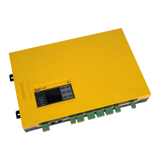
- Page 1 Manual ISOMETER® iso1685Dxx Insulation monitoring device for unearthed AC, AC/DC and DC power supplies (IT systems) up to AC 1000 V/DC 1500 V or AC 200 V/DC 3000 V Software versions iso1685DPxx: D0484 V2.0x, D0485 V1.0x iso1685D-HVxx: D0588 V2.0x, D0589 V1.0x iso1685DP_D00272_03_M_XXEN/08.2017...
- Page 2 E-Mail: info@bender.de Web: www.bender.de Customer service Service-Hotline: 0700-BenderHelp (Telephone and Fax) Carl-Benz-Straße 8 • 35305 Grünberg • Germany © Bender GmbH & Co. KG Tel.:+49 6401 807-760 All rights reserved. Fax:+49 6401 807-629 Reproduction only with permission of the publisher.
-
Page 3: Table Of Contents
Inhaltsverzeichnis 1. Important information ..............3 4. Device overview ................11 1.1 How to use this manual ..........3 4.1 Dimensions. - Page 4 Table of contents Table of contents 6.3.8 TEST ............21 11.
-
Page 5: Important Information
Bender devices WARNING • Extended guarantee for Bender devices, which includes an in-house repair service or replacement devices at no extra cost This signal word indicates a low-level risk that can result in minor or... -
Page 6: Field Service
*Available from 7.00 a.m. to 8.00 p.m. 365 days a year (CET/UTC+1) **Mo-Thu 7.00 a.m. - 8.00 p.m., Fr 7.00 a.m. - 13.00 p.m. For more information on the disposal of Bender devices, refer to our homepage at www.bender-de.com -> Service & support. -
Page 7: Safety Instructions
Part of the device documentation in addition to this manual is the enclosed "Safety in- When opening the device, you may come into contact with live parts. structions for Bender products". Switch off the mains voltage before opening the device! DANGER 2.2 Work activities on electrical installations. -
Page 8: Address Setting And Termination
Safety instructions Safety instructions 2.5 Intended use Prevent measurement errors! When a monitored IT system contains galvanically coupled DC circuits, an insulation fault can only be detected correctly if the rectifier valves (e.g. rectifier diode, thyristors, IGBTs, frequency inverters, …) carry a minimum Only qualified personnel are permitted to carry out the work necessary current of >... -
Page 9: Function
3. Function Function 3.1 Features 3.3 Function description • Insulation monitoring of IT systems up to Insulation monitoring is carried out using an active measuring pulse which is superim- posed onto the IT system to earth via the integrated coupling. When the insulation resist- iso1685DP-425 AC 1000 V/DC 1500 V iso1685D-HV-425 AC 2000 V/DC 3000 V ance between the IT system and earth falls below the set prewarning response value... -
Page 10: Insulation Monitoring
Function Function 3.3.1 Insulation monitoring If the EDS function is activated, the ISOMETER® starts the insulation fault location after the value has fallen below the response values R and R . When starting the insulation For insulation monitoring, a pulsating AC measuring voltage is superimposed onto the IT fault location, the LED "PGH on"... -
Page 11: Deactivating The Device
Function Function 3.3.4 Deactivating the device 3.5 Self test When the device is deactivated, the coupling unit of the device is galvanically isolated from the system being monitored. 3.5.1 Self test after connection to the supply voltage The device does not measure the insulation resistance, the message Device inactive ap- Once connected to the supply voltage, all internal measurement functions, the compo- pears on the display. -
Page 12: Automatic Self Test
Function Function 3.5.2 Automatic self test All supply voltages are continuously monitored. The following tests are continuously car- ried out in the background: • Connection E-KE • Temperature monitoring of coupling and locating current injector A self test is automatically run at 24-hour intervals. During the automatic self test, the alarm relays K1 (11-12-14) and K2 (21-22-24) are not switched. -
Page 13: Device Overview
4. Device overview 4.1 Dimensions 5,2 mm iso1685 ® ISOMETER PGH ON 106 mm 39,8 mm 40,75 mm 55,7 mm 51 mm 368 mm 383 mm 401,5 mm iso1685DP_D00272_03_M_XXEN/08.2017... -
Page 14: Connections
Device overview 4.2 Connections A, B, S RS-485 bus connection (A,B) 31, 32, 34 protocol: BMS Relay output for 11, 12, 14 A1, A2 CAN 1 S= PE potential Supply voltage U DC 24 V internal Relay output for CAN 2 Connect one end of device errors alarm insulation... -
Page 15: Display And Operating Elements
Device overview Device overview 4.3 Display and operating elements 4.3.2 Device buttons You can adjust the device settings in the respective menu using the menu buttons. De- pending on the menu entry, one of the options displayed below is assigned to the but- tons. -
Page 16: Installation And Connection
5. Installation and connection Installation and connection 5.1 Installation This signal word indicates a low-level risk that can result in minor or Install the device using four M5 screws, refer also to the dimension diagram where the moderate injury or damage to property if not avoided. drilling holes are illustrated (see "Dimensions"... -
Page 17: Step-By-Step Connection Of The Isometer
Installation and connection Installation and connection 5.2.2 Step-by-step connection of the ISOMETER® 5.2.3 Connecting the EDS to the ISOMETER® iso1685DP Connect the device according to the wiring diagram. Risk of malfunctions due to excessive locating current on sensitive Proceed as follows: system parts! 1. -
Page 18: Connection To An Ac System
Installation and connection 5. 3 Connection to an AC system L1/+ L2/- L1/+ L2/- PGH ON k I kT IT E KE A1 A2 A B S 31 32 34 21 22 24 11 12 14 I2+ I2- I1+ I1- BMS-Master iso1685DP_D00272_03_M_XXEN/08.2017... -
Page 19: Connection Example Of The Isometer® With An Insulation Fault Locator (Eds440/441-L) To A 3Ac System
Installation and connection 5.4 Connection example of the ISOMETER® with an insulation fault locator (EDS440/441-L) to a 3AC system L1/+ L2/- to the to the loads loads A1/+ A2/- EDS440 EDS440 ISOSCAN® ISOSCAN® TEST CHANNELS RESET PGH ON SERVICE ALARM SLAVE ADDRESS ∆... -
Page 20: Connection Example Of The Isometer® With An Insulation Fault Locator (Eds460) To An Ac System
Installation and connection 5.5 Connection example of the ISOMETER® with an insulation fault locator (EDS460) to an AC system L1/+ L2/- L1/+ L2/- to the to the loads loads EDS46…L MONITOR TEST SLAVE ADDRESS ALARM ERROR CODE) RESET PGH ON I2+ I2- I1+ I1- A B S k I kT IT... -
Page 21: Commissioning
6. Commissioning Commissioning 6. 1 Commissioning flow chart insulation fault monitoring 6. 2 Commissioning flow chart insulation faullt location (only iso1685DP) System = IT system ? iso1685Dxx not suitable Make sure that the system is Install the insulation fault locator disconnected from any electrical and the appropriate CTs source before connecting the device! -
Page 22: Initial Commissioning
Commissioning Commissioning 6.3 Initial commissioning 6.3.3 Setting the profile In order to optimally adapt the insulation monitoring device to the system to be moni- Follow the instructions of the commissioning wizard on the display. tored, select a profile here that suits your system. For an overview of the profiles, refer to Use the device buttons to navigate. -
Page 23: Setting Response Value Ran2 For Alarm 2
Commissioning Commissioning 6.3.5 Setting response value for Alarm 2 6.3.8 TEST The response value for the main alarm can be set here. Set the mode for the insulation fault location to manual, automatic or 1 cycle. For further A value of 50 Ω/V is recommended for the main alarm. information, refer to “Mode”... -
Page 24: Commissioning Eds (Only Iso1685Dp)
Commissioning Commissioning 6.5 Commissioning EDS (only iso1685DP) Proceed as follows to put into operation an EDS after commissioning the ISOMETER®: 1. Set the mode for the insulation fault location to manual, automatic or 1 cycle. For a description of the different modes, refer to “Mode”... -
Page 25: Display
7. Display Display 7.1 Standard display 7.2 Fault indication (active) During normal operation, the ISOMETER® displays the message OK and below, the cur- An active fault is displayed by The upper part of the display becomes orange and rently measured insulation resistance. displays the fault message. -
Page 26: Fault Indication (Inactive)
Display Display 7.3 Fault indication (inactive) 7.4 Acknowledging a fault message An inactive fault is displayed by . If several faults have occurred, the number of faults In order to acknowledge the fault message and return to the ISOMETER®'s standard dis- will also be indicated. -
Page 27: Data - Isograph
Display Display 7. 5 Data - isoGraph 7. 7 Insulation fault location The isoGraph represents the chronological sequence of the insulation resistance over When the EDS mode is activated, the ISOMETER® indicates the message "Ins. fault locat.". time. Below, it indicates which EDS mode is activated. On the right side it indicates the polarity This graphical representation can be displayed over the following time periods: hour, change of the measuring pulses including the pause in between. -
Page 28: Menu
8. Menu Menu 8. 1 Overview of the device menu 8. 2 Operation and Navigation Navigate through the device menu using the device buttons. The functions of the device 1. Alarm settings buttons are described in the chapter “Device buttons” auf Seite 1. -
Page 29: Settings
9. Settings Settings The settings of the ISOMETER® are explained in the order of the device menu. (1.2) Profile 1.0 Alarm settings Adapt the area of application of the ISOMETER® to your system profile. For a description of the profiles, refer to “Device profiles”... - Page 30 Settings Settings (1.4) Device Set the ISOMETER® insulation resistance measurement function to active or inactive: •Active The device is active. Reaction Reaction Impulse on Impulse off •Inactive The device DOES NOT measure the insulation resistance and is disconnected from the system to be monitored (system <...
- Page 31 Settings Settings (1.6.1.4) Function (1.7.1.2) Operating mode The parameters for the function of the digital inputs of the ISOMETER® can be set The relay mode can be adapted to the application: differently: •N/C Normally closed - N/C operation contacts11-12-14/ 21-22-24 (The alarm relay is energised during normal opera- •off Digital input without function tion).
- Page 32 Settings Settings (1.7.3.2) Function 1 (2.1) Mode The following parameters can be set: To locate insulation faults, select one of the four available modes for insulation fault location. •off The insulation fault location is deactivated. •off The function is not used. •Manual In manual mode, the insulation fault location starts immediately.
- Page 33 Settings Settings (2.2) Current 3.0 Data measured values The ISOMETER® stores certain measured values for a specific period of time. You can view Risk of malfunctions due to excessive locating current on sensitive these data at the "Data meas. values" menu item. Navigate through the different views system parts! using the buttons:...
- Page 34 Settings Settings (6.1) Language (6.2.3) Summer time Choose the language to be displayed by the ISOMETER®. For example, you can set the lan- Summer time can be considered in the following settings: guages: •off No automatic change between summer time and standard time. •German •DST Daylight Saving Time...
- Page 35 In the commissioning menu, you can open the ISOMETER®'s commissioning wizard again. menu: (6.7) Service (6.3.1) BMS The service menu can only be accessed by Bender service staff. Set the parameters for communication with other devices via the BMS bus. 7.0 Info (6.3.1.1) BMS address The ISOMETER®'s current settings can be viewed in the Info menu.
-
Page 36: Factory Settings
Settings Settings 9.2 Factory settings Value Response values, alarms and profile Parameter Status Value Parameter BMS address Status BMS termination Measurement method Power circuits Insulation response value R 40kΩ Digital inputs Insulation response value R 10kΩ Value Parameter Status Fault memory Coupling monitoring Mode (operating mode): active high Digital input 1... -
Page 37: Device Communication Via The Bms Bus
10. Device communication via the BMS bus Device communication via the BMS bus 10.1 RS-485 interface with BMS protocol The RS-485 interface, galvanically isolated from the device electronics, serves as a physi- cal transmission medium for the BMS protocol. When an ISOMETER® or other bus-capable RS-485 CAN 2 CAN 2... -
Page 38: Bms Protocol
10.3 BMS protocol • Switch the supply voltage on This protocol is an essential part of the Bender measuring device interface (BMS bus pro- • Assign the master function and address 1 to a bus-capable device tocol). Data transmission generally makes use of ASCII characters. -
Page 39: Alarm And Operating Messages Via The Bms Bus
Device communication via the BMS bus Device communication via the BMS bus 10.7 Alarm and operating messages via the BMS bus 10.7.2 Operating messages Messages are transmitted to a maximum of 12 BMS channels. All alarm and operating Message Channel Description messages that may occur are described below. -
Page 40: Error Codes
Device communication via the BMS bus Device communication via the BMS bus 10.7.4 Error codes Component The following list contains all relevant error codes output via the BMS bus. The right-hand Fault Action error code column describes the relevant action to be taken in each case. Programme sequence insulation 9.72 System... -
Page 41: Insulation Fault Location (Only Iso1685Dp)
11. Insulation fault location (only iso1685DP) Insulation fault location (only iso1685DP) 11.1 General description 11.4 Starting and stopping the insulation fault location An additional function of the ISOMETER® in combination with the EDS is the selective in- The insulation fault location can be started and stopped via different interfaces: sulation fault location. -
Page 42: Device Profiles
12. Device profiles System leakage Measuring Mains frequency Description capacitance voltage Main circuits without dynamic frequency changes. Power circuits DC, 15…460 Hz 0…150 μF ±50 V The universal profile is suitable for all systems primarily with constant mains frequencies and extraneous DC voltages. -
Page 43: Alarm Messages
Device error x Internal device error • Switch the supply voltage off and on SERVICE is lit • Contact Bender service Overtemperature • Check mains voltage level. The device connects itself again Overtemperature coupling terminal L1/+ or L2/– SERVICE is lit... -
Page 44: Diagrams
14. Diagrams 14.1 Response time profile Power circuits (p o Ce 1μF Ce 10μF Ce 100μF 1000 Response value Ran [k ] iso1685DP_D00272_03_M_XXEN/08.2017... -
Page 45: Response Time Profile High Capacitance
Diagrams 14.2 Response time profile High capacitance (p o 1000 Ce 1μF Ce 50μF Ce 100μF Ce 500μF Response value Ran [k ] iso1685DP_D00272_03_M_XXEN/08.2017... -
Page 46: Response Time Profile Inverter > 10 Hz
Diagrams 14.3 Response time profile Inverter > 10 Hz (p o Ce 1μF Ce 10μF Ce 100μF 1000 Response value Ran [k ] iso1685DP_D00272_03_M_XXEN/08.2017... -
Page 47: Response Time Profile Inverter < 10 Hz
Diagrams 14.4 Response time profile Inverter < 10 Hz (p o Ce 1μF Ce 10μF Ce 100μF 1000 Response value Ran [k ] iso1685DP_D00272_03_M_XXEN/08.2017... -
Page 48: Response Time Profile Fast 2000 Μf
Diagrams 14.5 Response time profile Fast 2000 μF (p o : & 2000μF) 1000 Ce 1μF Ce 10μF Ce 100μF Ce 1000μF Ce 2000μF Response value Ran [k ] iso1685DP_D00272_03_M_XXEN/08.2017... -
Page 49: Leakage Capacitance
Diagrams 14.6 Leakage capacitance & 1000 & 5 0 0 Fault resistance [k ] iso1685DP_D00272_03_M_XXEN/08.2017... -
Page 50: Technical Data
15. Technical data Technical data 15.1 Tabular data iso1685Dxx Relative uncertainty (10 kΩ…1 MΩ) (acc. to IEC 61557-8)......................±15 % Relative uncertainty (0.2 kΩ…< 10 kΩ)........................±200 Ω ±15 % ( )* = Factory settings Hysteresis ......................................25 % Insulation coordination acc. to IEC 60664-1/IEC 60664-3 Time response Insulation coordination according to IEC 60664-1 Response time t... -
Page 51: Standards And Certifications
Technical data Technical data Switching elements Other Switching elements....3 changeover contacts: K1 (insulation fault alarm 1), K2 (insulation fault alarm 2), K3 (device error) Operating mode ..............................continuous operation Operating principle K1, K2 ..................N/C operation or N/O operation (N/C operation)* Position of normal use.......................... - Page 52 Index Device features 7 Ableitkapazität 47 DIP switch 13 Address setting 7 Display 23 Alarm Fault display (active) 23 Messages 41 Fault display (inactive) 24 Alarm messages 37 Fault memory 24 Alarm relays 8 History memory 25 and certifications 49 Signal quality of the measurement 23 Ansprechzeit Display and operating elements 13...
- Page 53 Index Index Alarm 27 Mains frequency 40 Basic settings 31 Measured value transmission 9 Coupling monitoring 28 Measured values 31 Date and time 20, 32 Memory card 13 Inputs 28 Interface 33 Language 20, 32 Operating elements Manual test 31 Button/Key 13 Measured values 31 DIP switch 13...
- Page 56 Bender GmbH & Co. KG Kundendienst Postfach 1161 • 35301 Grünberg • Germany Service-Hotline: 0700-BenderHelp (Telefon und Fax) Londorfer Straße 65 • 35305 Grünberg • Germany Carl-Benz-Straße 8 • 35305 Grünberg • Germany Tel.: +49 6401 807-0 Tel.: +49 6401 807-760...
Need help?
Do you have a question about the ISOMETER iso1685D Series and is the answer not in the manual?
Questions and answers