
Related Manuals for Bender ISOMETER iso165C


Summary of Contents for Bender ISOMETER iso165C
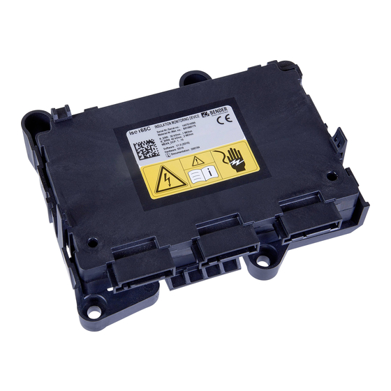
- Page 1 Manual ISOMETER® iso165C iso165C-1 Insulation Monitoring Device (IMD) for unearthed DC drive systems (IT systems) in electric vehicles iso165C_D00154_03_M_XXEN/01.2019...
- Page 2 E-Mail: info@bender.de Web: www.bender.de Customer service Service hotline: 0700-BenderHelp (Telephone and Fax) Carl-Benz-Straße 8 • 35305 Grünberg • Germany © Bender GmbH & Co. KG Tel.:+49 6401 807-760 All rights reserved. Fax:+49 6401 807-629 Reprinting only with permission of the publisher.
-
Page 3: Table Of Contents
Table of contents 1. Important information ..............5 6. Operation ..................15 1.1 How to use this manual ..........5 6.1 Messages. - Page 4 Table of contents 7.2.3.11 S_IMC_GET_MANUFACTURER .............19 7.3.24 D_VIFC_IMC_ALIVE ......... . .24 7.2.3.12 S_VIFC_GET_STATUS ................20 7.3.25 D_VIFC_STATUS .
-
Page 5: Important Information
Bender devices This signal word indicates a low level risk that can result in minor or mod- • Extended warranty for Bender devices with in-house repair service or replacement erate injury or damage to property if not avoided . device at no extra cost... -
Page 6: Training Courses
Sale and delivery conditions can be obtained from Bender in printed or electronic format. The directive on waste electrical and electronic equipment (WEEE directive) and the di- rective on the restriction of certain hazardous substances in electrical and electronic 1.5 Inspection, transport and storage... -
Page 7: Safety Information
Part of the device documentation in addition to this manual is the enclosed "Safety in- fore commissioning the system. It is necessary to examine whether the initial settings structions for Bender products". meet the requirements of the IT system. Risk of electrocution due to electric shock! -
Page 8: Function
3. Function Function Due to its space saving design and optimized measurement technology, the device is op- 3.1 Device features timized for use in hybrid or fully electric vehicles. The device meets the increased auto- motive requirements with regard to environmental conditions (e.g. temperatures and •... -
Page 9: Self Test
Function Function The IMC consists of the HV connectors with HV coupling relays, the measurement circuit and a microcontroller to analyse the measurement results. It generates internal alarm in- formation from the measurement results, which is coded to produce the "Alive" signal mentioned previously. -
Page 10: Dimensions
4. Dimensions 4.1 Device dimensions 141.82 ±2 ±0.6 43.2 ±1 Max. permissible unevenness between the mounting points iso165C_D00154_03_M_XXEN/01.2019... -
Page 11: Enclosure And Mounting
4.2 Enclosure and mounting Section view A-A Scale: 2:1 (ø 11) recommended screws (not included) 4 x M5 fastening torque: 2.25 ± 0.25 Nm Position Component Properties PBT GF30 black Housing UL Standard: UL94 V0 Connector pin Cu-alloy, tin plated Label White Polyester foil PBT GF30 black... -
Page 12: Connection
5. Connection Connection 5.1 Connection conditions The wiring should be carried out in a way that prevents a short circuit from happening. Risk of electric shock! The terminals HV1 ± / HV2 ± may have nominal voltages measuring up to 5.2 Connectivity 600 V. -
Page 13: Connector Pin Assignment
Connection Connection 5.2.1 Connector pin assignment 5.2.2 Wiring diagram 100 Ω/2.2 kΩ resistance at HST_1/HST_2 Connector/function Pin no. Signal T_31_KE_2 (vehicle internal earthing structure) reserved HST_1/HST_2 HST_2 (High-side driver 2, 100 Ω iso Error) - iso165C-1 only Connector 1 (LV) for: HST_1 (High-side driver 1, •... -
Page 14: Typical Application
Connection 5.3 Typical application RESS 1 RESS 2 ISO DC Inv1 Inv2 Inv3 Inverter Inv1 Inv2 Inv3 ISO AC EV Inlet BAT1 BAT3 BAT1 BAT3 Con1 Con2 Con3 BAT4 Con1 Con2 Con3 BAT4 BAT2 BAT2 Electrical Chassis / Protective equipotential bonding 5.3.1 Special application notes •... -
Page 15: Operation
6. Operation Operation 6.3 IMD_Request 6.1 Messages IMD_Request is a request to the ISOMETER® and will always generate an answer message Communication between a requesting instance in the vehicle environment and the ISO- IMD_Response. It can handle Control (CTL), SET and GET commands. METER®... -
Page 16: Example
Operation Operation 6.4 IMD_Response GET commands IMD_Response is generated exclusively as an answer to the IMD_Request command. The DBC command description Locked system guarantees that every request is answered with a response if the IMD_Request is S_VIFC_DUMMY accepted by the queue implementation. The response can have one of two frame for- 0x37 S_IMC_GET_STATUS mats: a valid response is returned in the event the request can be successfully answered. -
Page 17: Command And Data Value Descriptions
7. Command and data value descriptions Command and data value descriptions 7.2 Command descriptions 7.1 Naming convention The message parameters are coded in bytes 2 to 5 and provide the possibility to enhance 7.1.1 Signal naming the request or response with additional information. If no additional message parameters are listed in this chapter the parameter should be initialized with '0'. -
Page 18: S_Vifc_Ctl_Measurement
Command and data value descriptions Command and data value descriptions 7.2.1.4 S_VIFC_CTL_MEASUREMENT 7.2.2.4 S_VIFC_SET_HV_RELAIS This command is a request to select the IMD measurement mode. This command is a request to change the state of the HV relays in the HV coupling network. -
Page 19: S_Imc_Get_R_Iso_Err_Thr
Command and data value descriptions Command and data value descriptions 7.2.3.4 S_IMC_GET_R_ISO_ERR_THR 7.2.3.8 S_IMC_GET_HV_2 This command requests the insulation fault (error) threshold. This command requests the HV value between HV2_POS and HV2_NEG. IMD_Request IMD_Response IMD_Request IMD_Response 0x32 0x32 0x3A 0x3A DataWord1 D_IMC_R_ISO_ERR_THR DataWord1... -
Page 20: S_Vifc_Get_Status
Command and data value descriptions Command and data value descriptions 7.2.3.12 S_VIFC_GET_STATUS 7.2.3.16 S_VIFC_GET_LOCK This command requests the internal status of the VIFC. This signal requests the locking state of the ISOMETER® iso165C. IMD_Request IMD_Response IMD_Request IMD_Response 0xDC 0xDC 0xE0 0xE0 DataWord1 D_VIFC_STATUS... -
Page 21: D_Imc_R_Iso_Wrn_Thr
Command and data value descriptions Command and data value descriptions 7.3.3 D_IMC_R_ISO_WRN_THR Description Status This data value represents the threshold that causes an insulation warning when the in- Reserved sulation resistance is lower than this value. Reserved Unit kΩ Reserved Reserved 300 (for iso165C) Default... -
Page 22: D_Imc_R_Iso
Command and data value descriptions Command and data value descriptions 7.3.7 D_IMC_R_ISO 7.3.11 D_IMC_MANUFACT_DATA This data value represents the mean insulation resistance measured by the IMC. This data value represents the ASCII code of a character from the manufacturer's string. Unit kΩ... -
Page 23: D_Imc_Version
Command and data value descriptions Command and data value descriptions 7.3.15 D_IMC_VERSION 7.3.19 D_VIFC_LOCK_MODE This data value represents the software version of the IMC. This data value represents the current state of the ISOMETER® iso165C locking mode. Value Description Value Description Data3 Minor version... -
Page 24: D_Vifc_Version
Command and data value descriptions Command and data value descriptions 7.3.23 D_VIFC_VERSION 7.3.25 D_VIFC_STATUS This data value represents the software version of the VIFC. This data value represents the status state of the VIFC. Value Description Description Status Data3 Minor version 0 = Activated Insulation measurement 1 = Deactivated... -
Page 25: D_Imd_Error_Code
Command and data value descriptions Command and data value descriptions 7.3.26 D_IMD_ERROR_CODE 7.3.27 D_IMD_FAILED_CMD This data value represents the IMC and VIFC error codes in the error frame. This data value represents the frame command identification of a failed IMC command. IMC error codes Value Description... -
Page 26: Data
Measurement time after power on (and after HV relays are closed) 3 s (<1 μF/150 kΩ) Measuring circuit Switch-off time t (DCP) Measurement method ........................Bender DCP technology (Changeover R /2 - 10 MΩ; at C = 1 μF; U = 600 V DC) ............t ≤... -
Page 27: Ordering Data
Data Data Other 8.3 Standards - corresponding norms and regulations Operating mode .............................Continuous operation 8.3.1 General Degree of protection................................ IP5K0 Software version IEC 61557-8 2007-01; IEC 60664-1 2004-04; ISO 6469-3 2001-11; ISO 23273-3 2006-11 iso165C ......................V1.0 - Release S010 (VIFC: V5.0 , IMC V5.0) 8.3.2 EMC iso165C-1......................V2.0 - Release S010 (VIFC: V10.0 , IMC V5.0) CISPR 25;... -
Page 28: Index
INDEX Accessories 27 Data value descriptions 20 Device CAN interface 9 Command component housing and mounting 11 Control (CTL) 17 description 8 GET 16 features 8 SET 15 functional description 8 Command value description 17 HS-CAN bus 8 GET 18 IMC 8 naming 17 intended use 7... - Page 29 Safety 7 work activities 7 Standards EMC 27 environmental 27 general 27 Technical data 26 connectors 26 other 27 UART 8 Wiring diagram 100 Ω/2.2 kΩ resistance 13 iso165C_D00154_03_M_XXEN/01.2019...
- Page 32 Bender GmbH & Co. KG Customer service Postbox 1161 • 35301 Grünberg • Germany Service-Hotline: 0700-BenderHelp (Telephone and Fax) Londorfer Straße 65 • 35305 Grünberg • Germany Carl-Benz-Straße 8 • 35305 Grünberg • Germany Tel.: +49 6401 807-0 Tel.: +49 6401 807-760...
Need help?
Do you have a question about the ISOMETER iso165C and is the answer not in the manual?
Questions and answers