User Manuals: Bender ISOMETER iso1685DP Device
Manuals and User Guides for Bender ISOMETER iso1685DP Device. We have 2 Bender ISOMETER iso1685DP Device manuals available for free PDF download: Manual

Bender ISOMETER iso1685DP Manual (56 pages)
Insulation monitoring device
Brand: Bender
|
Category: Measuring Instruments
|
Size: 7 MB
Table of Contents
Advertisement
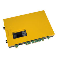
Bender ISOMETER iso1685DP Manual (56 pages)
Insulation monitoring device for unearthed AC, AC/DC and DC power supplies IT systems up to AC 1000 V/DC 1500 V or AC 200 V/DC 3000 V
Brand: Bender
|
Category: Measuring Instruments
|
Size: 7 MB