Table of Contents
Advertisement
Quick Links
Advertisement
Table of Contents

Subscribe to Our Youtube Channel
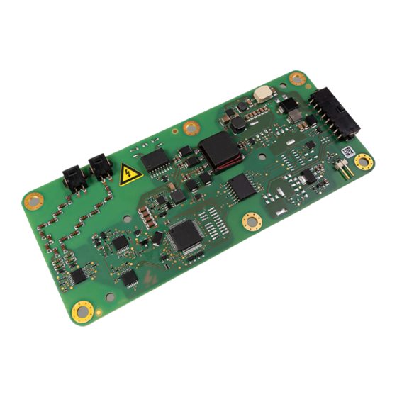
Summary of Contents for Bender ISOMETER iso175
- Page 1 Kurzanleitung DE Quick-start guide EN ISOMETER® iso175 Isolationsüberwachungsgerät für ungeerdete Antriebssysteme (IT-Net- ze) in Straßenfahrzeugen Insulation monitoring device for unearthed drive systems (IT systems) in road vehicles iso175_D00415_01_Q_DEEN/11.2023...
-
Page 2: Ordering Information
Kurzanleitung „Sicher- enclosed “Safety instructions for heitshinweise für Bender- Bender products“ and the manual, Produkte“ und das dazugehörige which can be downloaded from Handbuch, herunterladbar unter https://www.bender.de/en/ser- https://www.bender.de/service- vice-support/downloads. support/downloadbereich. -
Page 3: Bestimmungsgemäße Verwendung
Isolationswiderstand des HV-Netzes. Je communicates (Bender protocol, nach Variante kommuniziert es über CAN (Bender SAE J1939 protocol) with a higher-level system. Protokoll, SAE J1939 Protokoll) mit einer übergeordne- ten Stelle. Other installation locations in the vehicle or in in- Andere Einbauorte im Fahrzeug oder Branchen dustry sectors such as e. -
Page 4: Gerätespezifische Sicherheitshinweise
ISOMETER® iso175 Gerätespezifische Sicherheitshinweise Device-specific safety instructions voltage ocHspannung Lebensgefahr Danger to life Das ISOMETER® ist galvanisch mit der HV- The ISOMETER® is galvanically connected to Sammelschiene des Fahrzeuges verbunden. An the HV busbar of the vehicle. When it is instal- den elektronischen Kontakten des HV+ Steckers led, up to 1000 V are applied to the electronic und den umliegenden Bauteilen... - Page 5 ISOMETER® iso175 HINWEIS Wenn IT-Systeme galvanisch mitein- ADVICE Where IT systems are to be galvanically ander verbunden werden sollen, muss dies connected, this connection must be ensured by durch eine niederohmige Verbindung sicher- a low ohmic-resistance connection. Intrinsic di- gestellt werden. So können z.B. Diodenstrecken odes, such as body diodes of MOSFET transis- wie Bodydioden von MOSFET Transistoren den tors for instance, can adversely affect the insu-...
-
Page 6: Montage
ISOMETER® iso175 Montage Mounting Montage- und Steckverbindersätze sind nicht im Mounting and connector kits are not part of the Lieferumfang enthalten (siehe Bestellangaben scope of delivery (see ordering information „Zubehör“). “Accessories”). Befestigung Fastening • Einbaulage: beliebig, Durchbiegung siehe tabella- • Mouning direction: any, Deflection see tabular rische Daten unter Sonstiges data under Other •... - Page 7 ISOMETER® iso175 Steckverbinder* Pin-Nr. Beschreibung Connector* Pin-no. Describtion Netzspannung (L+) Mains voltage (L+) Netzspannung (L-) Mains voltage (L-) Versorgungsspannung - (Kl. 31) Supply voltage - (terminal 31) Versorgungsspannung + (Kl. 15) Supply voltage - (terminal 15) Erdanschluss (E) Earth connection (E) n.c.
- Page 8 ISOMETER® iso175 Inbetriebnahme Commissioning Nach Einbau und Anschluss des ISOMETER® muss die Once the ISOMETER® has been mounted and connected, Spannungsversorgung und das HV-Netz zugeschaltet the supply voltage and the HV system must be connec- werden. Die ordnungsgemäße Funktionalität kann wie ted.
-
Page 9: Measuring Range
ISOMETER® iso175 Messbereich Measuring range R_iso_corrected ..............0…35 MΩ R_iso_corrected ..............0…35 MΩ R_iso_original ...............0…50 MΩ R_iso_original ...............0…50 MΩ Messbereich Measuring range Isolation: R_iso_neg* ............0…50 MΩ Isolation: R_iso_neg* ............0…50 MΩ Isolation: R_iso_pos* ............0…50 MΩ Isolation: R_iso_pos* ............0…50 MΩ Voltage: HV-System Spannungsmessung ......0…1000 V Voltage: HV system voltage measurement ......0…1000 V Toleranz Voltage: HV-System Spannungsmessung ....±5 % ±... - Page 10 ISOMETER® iso175 HV-Anschluss HV connection Leitungslänge max................2 m Cable length, max ................2 m Leitungsquerschnitt ............AWG 20…24 Cable cross section ............AWG 20…24 validierter Kabeltyp ............AlphaWire 5875 Validated cable type ............AlphaWire 5875 Umwelt Environment Arbeitstemperatur ............-40…+105 °C Operating temperature ..........
-
Page 11: Normen Und Zulassungen
ISOMETER® iso175 Normen und Zulassungen Standards and approvals Das ISOMETER® iso175 wurde nach folgenden Normen The ISOMETER® iso175 has been developed in accordan- und Zulassungen entwickelt: ce with the following standards and approvals: • IEC 61010-1 • IEC 61010-1 • IEC 60664-1 •... - Page 12 Alle Rechte vorbehalten. 35305 Grünberg Nachdruck und Vervielfältigung nur mit Germany Genehmigung des Herausgebers. © Bender GmbH & Co. KG, Germany Subject to change! The specified Tel.: +49 6401 807-707 All rights reserved. standards take into account the edition emobility@bender.de...


Need help?
Do you have a question about the ISOMETER iso175 and is the answer not in the manual?
Questions and answers