Advertisement
Quick Links
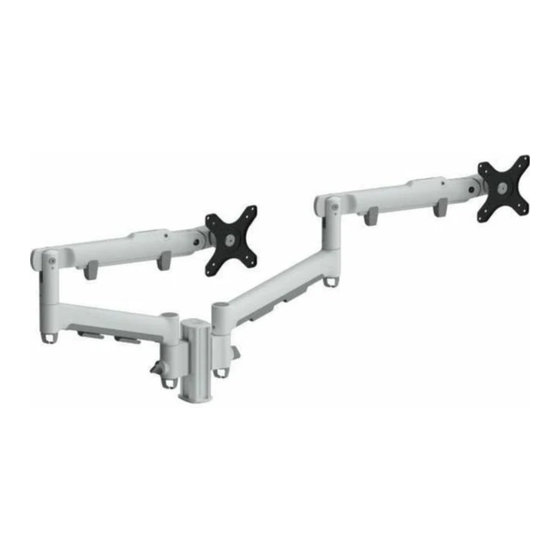
2 x Dynamic Arms on 135 Post with C-Clamp
COMPONENT CHECKLIST
A
AWM-LC
Post Clamp (x1)
CONTENTS
C-Clamp
Page 2
Page 3
135 Post
Page 6
Page 7
Post Clamp
Page 8
Page 9
Dynamic Arm
Page 10
Page 11
Page 12
Page 13
B
C
AWM-AD
AWM-P13
Dynamic Arm
135 Post
(x2)
(x1)
AWM-FC
Component Checklist
Clamp Installation
AWM-P13
Component Checklist
Post Installation
AWM-LC
Component Checklist
Post Clamp Installation
AWM-AD
Component Checklist
Arm Installation
Monitor Installation
Cable Management
Installation Guide
AWMS-2-D13-C
RANGE
D
AWM-FC
C-Clamp
(x1)
AWMS-2-D13-C | Page 1 of 13
Advertisement

Subscribe to Our Youtube Channel
Related Manuals for Atdec AWMS-2-D13-C


Summary of Contents for Atdec AWMS-2-D13-C
- Page 1 Page 7 Post Installation Post Clamp AWM-LC Page 8 Component Checklist Page 9 Post Clamp Installation Dynamic Arm AWM-AD Page 10 Component Checklist Page 11 Arm Installation Page 12 Monitor Installation Page 13 Cable Management AWMS-2-D13-C | Page 1 of 13...
- Page 2 (x1) IMPORTANT INFORMATION ! Please ensure this product is installed as per these installation instructions. ! This product is compatible with Atdec modular (AWM) products. ! The manufacturer accepts no responsibility for incorrect installation. AWMS-2-D13-C | Page 2 of 13...
- Page 3 3.5 Tighten the set screws firmly and evenly on both sides of the desk clamp bracket is positioned tight up against the mounting desk clamp bracket. surface edge M8 x 16mm Set Screw Desk Clamp Bracket Mounting surface AWMS-2-D13-C | Page 3 of 13 AWM-FC Page 2 of 4...
- Page 4 5.5 Tighten the set screws firmly and evenly on both sides of the desk clamp bracket is positioned tight up against the mounting desk clamp bracket surface edge M8 x 16mm Set Screw Desk Clamp Bracket Mounting surface AWMS-2-D13-C | Page 4 of 13 AWM-FC Page 3 of 4...
- Page 5 No portion of this document or any artwork contained herein should be reproduced in any way without the express written consent of Atdec Pty Ltd. Due to continuing product development, the manufacturer reserves the right to alter specifications without notice. ©20180502D...
- Page 6 IMPORTANT INFORMATION ! Please ensure this product is installed as per these installation instructions. ! This product is compatible with Atdec AWM Series products. ! The manufacturer accepts no responsibility for incorrect installation. AWMS-2-D13-C | Page 6 of 13...
- Page 7 No portion of this document or any artwork contained herein should be reproduced in any way without the express written consent of Atdec Pty Ltd. Due to continuing product development, the manufacturer reserves the right to alter specifications without notice. ©20180518E...
- Page 8 ! Please ensure this product is installed as per these installation instructions. ! This product is compatible with AWM Series Arms, Posts and Wall Channels. ! The manufacturer accepts no responsibility for incorrect installation. AWM-LC Page 1 of 2 AWMS-2-D13-C | Page 8 of 13...
- Page 9 No portion of this document or any artwork contained herein should be reproduced in any way without the express written consent of Atdec Pty Ltd. Due to continuing product development, the manufacturer reserves the right to alter specifications without notice. ©20180518A - E02...
- Page 10 ! Please ensure this product is installed as per these installation instructions. ! This product is compatible with Atdec AWM Series products. ! The Dynamic Arm (AWM-AD) requires a Channel Clamp (AWM-LC, sold separately) for installation on an AWM Post.
- Page 11 4.2 Ensure that the VESA head sits flush within 4.3 Push the lever down to secure the monitor arm. There should be no gap. it to the arm assembly Monitor arm No Gap AWMS-2-D13-C | Page 11 of 13 AWM-AD Page 2 of 4...
- Page 12 When installing subsequent installation faster. monitors, pre-tension the arm to the recorded amount, then fine-tune the tension by Marker following steps 6.3 to 6.5. AWMS-2-D13-C | Page 12 of 13 AWM-AD Page 3 of 4...
- Page 13 No portion of this document or any artwork contained herein should be reproduced in any way without the express written consent of Atdec Pty Ltd. Due to continuing product development, the manufacturer reserves the right to alter specifications without notice. ©20180521C the express written consent of Atdec Pty Ltd.
Need help?
Do you have a question about the AWMS-2-D13-C and is the answer not in the manual?
Questions and answers