Advertisement
Quick Links
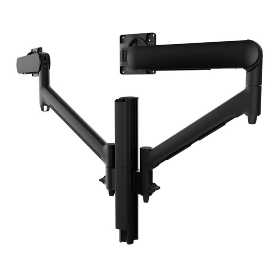
Dual Dynamic Monitor Arms on 400 Post
INDEX
Component Checklist
AWM 400 Post with Guide Marks
AWM-P40G
AWM Dynamic Arm for Post
AWM-ADTC
Cable Management
IMPORTANT INFORMATION
! Please ensure this product is installed as per these installation instructions.
! Do not remove or throw away the plastic sleeve on the arm link and channel clamp.
! The manufacturer accepts no responsibility for incorrect installation.
! This product is not suitable for outdoor use or mobile applications
! Do not over-tighten screws and adjustment points on product.
! Periodic adjustment to counterbalance and tilt tension may be required.
! VESA mounted accessories (such as mini PC brackets and mounts), offset VESA
locations, and unevenly weighted monitors (relative to the center of the VESA
mounting interface) exert additional leverage that can exceed the capacity of the
mount even though the monitor weight may be within the stated range. Please
contact Atdec if you would like further information.
Page 2
Installation Instructions
Page 3
Installation Instructions
Page 4
Page 6
Installation Guide
AWMS-2-D40
REQUIRED TOOLS
• Phillips Head Screwdriver
CAPACITY
Flat Monitors
2 - 8kg (4.4 - 17.6lbs)
Curved Monitors*
2 - 8kg (4.4 - 17.6lbs)
*Curved monitors with an overall
depth up to 140mm (5.5").
Monitor weight should be within
the weight range of all modular
elements that make up the complete
monitor mounting solution.
AWMS-2-D40 Page 1 of 7
Advertisement

Subscribe to Our Youtube Channel
Related Manuals for Atdec AWMS-2-D40


Summary of Contents for Atdec AWMS-2-D40
- Page 1 Please elements that make up the complete contact Atdec if you would like further information. monitor mounting solution. AWMS-2-D40 Page 1 of 7...
-
Page 2: Component Checklist
Below are the fixing options available for this solution. Fixing installation guides are supplied with the product or can be accessed through Atdec’s website, along with detailed product specifications. NOTE: Chosen desk fixing must be added to this solution code when ordering. - Page 3 Default Position 2. Lift 360° 1. Press NOTE: Rotation ring placement 180° depends on the position of the clamp on the post. The tag on Flipped the ring should always face Position toward the user. AWMS-2-D40 Page 3 of 7...
- Page 4 TIP! To allow monitor to be rotated with provided screws. (Alternatively, upside down, mount VESA head in 75x75 VESA interfaces use fasteners specified by the will require a Spacer the alternate orientation shown. monitor manufacturer.) Kit (sold separately) NOTE: Logo position AWMS-2-D40 Page 4 of 7...
- Page 5 9.1 Adjust the rotation tension using 4mm hex key. Adjustment may only be required for ultrawide monitors. LOOSEN DRIFTS HOLDS POSITION TIGHTEN 10. Removing monitor 10.1 Slide release switch up and click into unlocked position, then lift monitor away from the arm. AWMS-2-D40 Page 5 of 7...
- Page 6 12.2 Push cables into lower arm hook flaps. 12.3 Slide the remaining loose cable from the central gap up the arm. AWMS-2-D40 Page 6 of 7...
- Page 7 No portion of this document or any artwork contained herein should be reproduced in any way without the express written consent of Atdec Pty Ltd. Due to continuing product development, the manufacturer reserves the right to alter specifications without notice. ©20240604...
Need help?
Do you have a question about the AWMS-2-D40 and is the answer not in the manual?
Questions and answers