Table of Contents
Advertisement
Advertisement
Table of Contents

Related Manuals for logitrans ROTATOR SELFR


Summary of Contents for logitrans ROTATOR SELFR
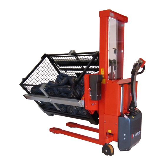
- Page 1 ROTATOR - SELFR/SELFSR_SELFRA/SELFSRA...
- Page 2 • Directive no. 2014/35/EC b) has been manufactured in conformance with the stipulations of the standard: • EN ISO 3691-1 Responsible for the technical dossier: Gitte Kirkegaard Name: Hillerupvej 35, DK-6760 Ribe Address: Signature: Gitte Kirkegaard, CEO, Logitrans A/S Ribe, 31.03.2021. B148 D217...
-
Page 3: Table Of Contents
Contents 1.0 Before the first lift....................4 2.0 Functions and identifications ................5 2.1 Box holder ........................6 2.2 Box holders with clamps ....................7 2.3 Box holder - adjustable (SELFRA/SELFSRA) .............7 3.0 How to operate the Rotator ................8 3.1 Pallet handling ......................8 3.2 Use of the Rotator .....................10 3.3 Handle functions ......................11 3.4 Remote control MR-1 / Lifting-Lowering-Rotation .............14... -
Page 4: Before The First Lift
1.0 Before the first lift... The Rotator is manufactured in accordance with safety directives. Among other subjects dealt with in this Instruction Manual are: • Proper application • Psysical limitations of the product • Risks with improper use Therefore please read this Instruction Manual carefully! -
Page 5: Functions And Identifications
2.0 Functions and identifications 1.Safety switch 2.Horn 3.Lift/Lower 4.Forward/Reverse 5.Multiflex function 6.Handle 7.Battery indicator/ hour counter 8.Emergency stop 9.Ignition key 10.Box holder with clamps 11.Box holder without clamps 12.Name plate, serial number 13.Remote control 14.User-Interface... -
Page 6: Box Holder
2.0 Functions and identifications 2.1 Box holder The Rotator can be equipped with one or two sets of box holders, adjusted for different box sizes. When loosening the screw (A), the box holder can be moved between the four different positions. NOTE! The screw has to be tightened, before using the product. -
Page 7: Box Holders With Clamps
2.0 Functions and identifications 2.2 Box holders with clamps If the box can fall off, or if it has to be tilted more than 60º, box holders with clamps have to be used. Box holders with clamps can grip, hold and rotate boxes with different heights. The clamps are to be tightened when the box is lifted from the floor. -
Page 8: How To Operate The Rotator
3.0 How to operate the Rotator 3.1 Pallet handling The Rotator functions as an ordinary stacker, when the forks are placed in horizontal position. For proper operation,stand behind the handle. - Page 9 3.0 How to operate the Rotator When handling closed pallets - use the Rotator with straddle legs! SELFSR SELFR...
-
Page 10: Use Of The Rotator
3.0 How to operate the Rotator 3.2 Use of the Rotator Insert key (1) and turn clockwise to switch on control current ready for function activation. Note!!! Emergency stop (2) must not be activated. Condition: The upper edge of the forks is lifted between 400 and 900 mm. The load can be rotated 360º... -
Page 11: Handle Functions
3.0 How to operate the Rotator NOTE! The load has to be supported sideways before tilting. 3.3 Handle functions The control functions of the Rotator are located in the handle (6). • The functions are dependent on the positions of the handle. Position A: Drive position •... - Page 12 3.0 How to operate the Rotator...
- Page 13 3.0 How to operate the Rotator 3.3.1 Multiflex-function Multiflex-function • This function makes it possible to drive the Rotator, even though the handle is in its upright, braked position (B) • The function requires two-handed operation, i.e. it must be performed deliberately •...
-
Page 14: Remote Control Mr-1 / Lifting-Lowering-Rotation
3.0 How to operate the Rotator 3.4 Remote control MR-1 / Lifting-Lowering-Rotation • The remote control is used for: • Lifting/lowering the forks/load • Rotating the forks/load Lifting / Loweering Press c to lift. Press d to lower. Rotation: Press for rotation in the direction of the arrow. -
Page 15: User-Interface Lui-1 Rotator
3.0 How to operate the Rotator 3.5 User-Interface LUI-1 Rotator User-Interface LUI-1 for: • Setting speed for rotation • Setting up to three stop position/angles in both rotation directions 3.6 Setting up User-Interface LUI-1 Rotator 3.6.1 Home screen When starting the machine/deactivating the emergency stop in User-Interface LUI-1, the home screen is shown on the display. - Page 16 3.0 How to operate the Rotator 3.6.2 Setup menu At home screen, press settings icon (SETUP) to go to setup menu. 1.Rotation Speed (SPEED) 2.Angle stop (STOPS) 3.Service menu (SERVICE) 4.Usage data (LOG) 5.Home screen (HOME) 3.6.3 Setting of rotation speed At the Setup menu, press “SPEED”...
- Page 17 3.0 How to operate the Rotator 3.6.4 Setting of stop position From the factory, the forks are set to rotate continuously. When the forks have rotated 360°, the machine stops rotating. If you want rotation to continue, it is necessary to release/press the rotation switch on the remote control again. It is possible to set up to three stop positions/angles for rotation in both directions.
-
Page 18: Battery Info Display
3.0 How to operate the Rotator 3.7 Battery Info display The display can show the following information: • The BDI or BOC – Battery state of charge • Machine operating hours • Fault codes/warnings • State of operation LED’s Upper 3-digit message field Wrench symbol Hourglass symbol Lower 6-digit message field... - Page 19 3.0 How to operate the Rotator 3.7.2 Machine operating hours 3 different operating hours are being logged: • ”TOTAL/KEY ON” hours - the total hours with power on the truck. • ”TRACTION” hours - the hours the traction motor has been in operation. •...
-
Page 20: Optimum Safety
4.0 Optimum safety ATTENTION!! Moving parts 4.1 Safety regulations • Never walk under a raised load! • Before lowering the forks, make certain that no foreign elements can hinder the free lowering of the forks • The Rotator is designed for use on an even and level floor •... -
Page 21: Avoid Overloads
4.0 Optimum safety 4.2 Avoid overloads The maximum load must not be exceeded. Remember, that the Rotator is designed for evenly distributed load, - goods on pallets etc. If the forks are point- loaded on one side, there is a risk of bending. NOTE! When driving with the truck, the forks should be placed in horizontal position. -
Page 22: Avoid Offset Loads
4.0 Optimum safety 4.3 Avoid offset loads The load must be evenly distributed. The maximum centre of gravity distance from the front of the fork mast (given on the truck) must not be exceeded. A greater distance reduces the level of safety and increases the risk of toppling. Goods on pallets, etc. - Page 23 4.0 Optimum safety Special version The top stop can be set to other intervals than between 400-900 mm. The height of the top stop depends on the width of the Rotator, as a wide Rotator can manage a larger sideways movement. E.g.
-
Page 24: Driving Loaded
4.0 Optimum safety 4.5 Driving loaded The load centre is never allowed to exceed the centre line of the wheels. The driving speed is reduced when lifting the forks above 400 mm. 4.6 Rotation with load The load centre is not allowed to be placed on the outside of the legs of the stacker, as this will cause a risk of turning over. -
Page 25: Emergency Stop
4.0 Optimum safety 4.7 Emergency stop The product has an emergency stop (2). When activating the emergency stop, the main current supply is switched off. • The movement of the forks stops immediately • Driving with the truck stops immediately •... -
Page 26: There Must Be A Current Supply
5.0 There must be a current supply... 5.1 Fuses - replacement There are four fuses in the electrical circuit, located behind the plate with this pictogram. • 60 Amp fuse for Rotator • 100 Amp fuse in the main supply from battery •... -
Page 27: Long Live The Rotator
6.0 Long live the Rotator Regular inspection and the replacement of worn or defective parts in good time will prolong the life of the Rotator. “Prevention is better than repair”, therefore ensure: • That the battery is fully charged every time •... -
Page 28: Oil Change
6.0 Long live the Rotator 6.2 Oil change Draining the oil: 1. Bring the unloaded forks down to the lowest position. 2. Most of the oil can be drained by loosening the hydraulic hose union in the bottom of the cylinder. Activate the hydraulic pump by pressure on the switch. The oil will run out. -
Page 29: Fork Adjustment
6.0 Long live the Rotator Gear motor of Rotator The gear motor has a ”short time under constant load” of 10 minutes (S2=10 minutes). This means that the motor is allowed to operate with the maximum load for 10 minutes. Hereafter it has to be cooled down to normal temperature. NOTE! The motor will be damaged by superheating, if it operates for a longer time or if it is not cooled down. -
Page 30: Adjustment Of Side Play
6.0 Long live the Rotator 6.6 Adjustment of side play 1. Screw (A) is loosened counter-clockwise, until resistancedisappears. 2. Turn the screw clockwise, until resistance appears. The following 1.5 to 2.5 turns of the screw will be a tightening of the spring (C). 3. -
Page 31: Adjusting The Rotator
6.0 Long live the Rotator 6.7 Adjusting the Rotator Tensioning the chains When the unloaded forks can be tilted manually approx. 5 cm, the chains should be tensioned. This is done by: 1. Removing the covers from the rotator carriage and the gear motor. 2. -
Page 32: Claning
6.0 Long live the Rotator Lubrication Support block To support the thrust ring, two support blocks (A) are placed behind the ring. The blocks have to press on the ring, and the back of the ring (B) has to be lubricated with grease, so that the blocks slide smoothly. -
Page 33: Fault Codes/Fault Location Key
7.0 Fault codes/Fault location key 7.1 Fault codes - Battery info display Code Description Solution Battery voltage too low Charge battery Power supply is missing Check fuses Controller overheated Contact the dealer Error main relais Contact the dealer For other error codes, contact your dealer. -
Page 34: Fault Location Key
7.0 Fault codes/Fault location key 7.2 Fault location key When the Rotator is used every day, adjustments and the replacement of worn parts might be necessary. Adjustments and minor repair can easily be made on the spot. Major repairs should, however, be carried through by the dealer who has a well-trained staff and the necessary special tools. - Page 35 Cause Remedy Oil deficiency See point 6.1/6.2 See separate Battery discharged instruction Fuse blown See point 5.1 10 Amp or 100 Amp See point 5.2 Cables defective See point 4.2 Max. load exceeded Air in hydraulic system See point 6.3 Pressure relief valve Contact incorrectly adjusted...
-
Page 36: Good Service After Purchase
• replacements of parts have been made incorrectly or original parts have not been used and consequential damages have arisen, • if the product is changed or accessories, not being approved by Logitrans, are used. • it can not be proved that a qualified technician has performed the service check according to the requirements stated in the instruction manual (see the back page). - Page 40 Periodic service and safety inspection Service inspection is required once each year, or at least for every 500 hours of operation. Safety inspection should be performed by the dealer or other qualified persons at least once each year, unless local regulations state otherwise.
Need help?
Do you have a question about the ROTATOR SELFR and is the answer not in the manual?
Questions and answers