Table of Contents
Advertisement
Quick Links
Advertisement
Table of Contents

Related Manuals for logitrans ROTATOR ELFR


Summary of Contents for logitrans ROTATOR ELFR
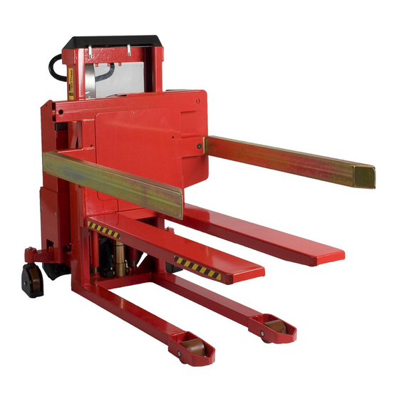
- Page 1 ROTATOR- ELFR/ELFSR_ELFRA/ELFSRA...
- Page 2 • Directive no. 2014/35/EC b) has been manufactured in conformance with the stipulations of the standard: • EN ISO 3691-5 Responsible for the technical dossier: Gitte Kirkegaard Name: Hillerupvej 35, DK-6760 Ribe Address: Signature: Gitte Kirkegaard, CEO, Logitrans A/S Ribe, 20.02.2020. B148 D142-3...
-
Page 3: Table Of Contents
Contents 1.0 Before the first lift....................4 2.0 Functions and identifications ................5 2.1 Box holder ........................... 6 2.2 Box holders with clamps ...................... 7 2.3 Box holder - adjustable (ELFRA/ELFSRA) ................7 3.0 How to operate the Rotator ................ -
Page 4: Before The First Lift
1.0 Before the first lift... The Rotator is manufactured in accordance with safety directives. Among other subjects dealt with in this Instruction Manual are: • Proper application • Psysical limitations of the product • Risks with improper use Therefore please read this Instruction Manual carefully! -
Page 5: Functions And Identifications
2.0 Functions and identifications Released position To release the brake: 1. Pull Braked position 2. Push 1. Handle 2. Lift/Lower 3. Emergency stop 4. Brake 5. User-Interface 6. Remote control 7. Box holder with clamps 8. Box holder without clamps 9. -
Page 6: Box Holder
2.0 Functions and identifications 2.1 Box holder The Rotator can be equipped with one or two sets of box holders, adjusted for different box sizes. When loosening the screw (A), the box holder can be moved between the four different positions. NOTE! The screw has to be tightened, before using the product. -
Page 7: Box Holders With Clamps
2.0 Functions and identifications 2.2 Box holders with clamps If the box can fall off, or if it has to be tilted more than 60º, box holders with clamps have to be used. Box holders with clamps can grip, hold and rotate boxes with different heights. The clamps are to be tightened when the box is lifted from the floor. -
Page 8: How To Operate The Rotator
3.0 How to operate the Rotator 3.1 Pallet handling The Rotator functions as an ordinary stacker, when the forks are placed in horizontal position. For proper operation, stand behind the handle. Push/pull - lift/lower ELFSR When handling closed pallets - use the Rotator with straddle legs! ELFR... -
Page 9: Use Of The Rotator
3.0 How to operate the Rotator 3.2 Use of the Rotator Condition: The upper edge of the forks is lifted between 400 and 900 mm. The load can be rotated 360º with one adjustable stop in every side. Note! To continue the tilt function from the horizontal position, the tilt switch has to be released and activated in the requested tilt direction. -
Page 10: Remote Control Mr-1 / Lifting-Lowering-Rotation
3.0 How to operate the Rotator 3.3 Remote control MR-1 / Lifting-Lowering-Rotation The remote control is used for: • Lifting/lowering the forks/load • Rotating the forks/load Lifting / Loweering Press to lift. Press to lower. Rotation: Press for rotation in the direction of the arrow. From the factory, the rotation is set to rotate continuously. -
Page 11: User-Interface Lui-1 Rotator
3.0 How to operate the Rotator 3.4 User-Interface LUI-1 Rotator User-Interface LUI-1 for: • Setting speed for rotation • Setting up to three stop position/angles in both rotation directions 3.5 Setting up User-Interface LUI-1 Rotator 3.5.1 Home display When starting the machine/deactivating the emergency stop in User-Interface LUI-1, home display is shown. -
Page 12: Display For Setup
3.0 How to operate the Rotator 3.5.2 Display for Setup At home display, press Setup and the following is shown. 1.Speed (SPEED) 2.Angle stop (STOPS) 3.Service (SERVICE) 4.Output data (LOG) 5.Home display (HOME) 3.5.3 Setting of rotation speed At the Setup display, press “SPEED” and the following is shown. 1. -
Page 13: Setting Of Stop Position
3.0 How to operate the Rotator 3.5.4 Setting of stop position From the factory, the forks are set to rotate continuously. When the forks have rotated 360°, the machine stops rotating. If you want rotation to continue, it is necessary to release/press the rotation switch on the remote control again. It is possible to set up to three stop positions/angles for rotation in both directions. -
Page 14: Optimum Safety
4.0 Optimum safety ATTENTION Moving parts 4.1 Safety regulations • Never walk under a raised load! • Before lowering the forks, make certain that no foreign elements can hinder the free lowering of the forks • The Rotator is designed for use on an even and level floor •... -
Page 15: Avoid Overloads
4.0 Optimum safety 4.2 Avoid overloads The maximum load must not be exceeded. Remember, that the Rotator is designed for evenly distributed load, - goods on pallets etc. If the forks are point- loaded on one side, there is a risk of bending. NOTE! When driving with the truck, the forks should be placed in horizontal position. -
Page 16: Avoid Offset Loads
4.0 Optimum safety 4.3 Avoid offset loads The load must be evenly distributed. The maximum centre of gravity distance from the front of the fork mast (given on the truck) must not be exceeded. A greater distance reduces the level of safety and increases the risk of toppling. Goods on pallets, etc. - Page 17 4.0 Optimum safety Special version The top stop can be set to other intervals than between 400-900 mm. The height of the top stop depends on the width of the Rotator, as a wide Rotator can manage a larger sideways movement. E.g.
-
Page 18: Driving Loaded
4.0 Optimum safety 4.5 Driving loaded The Rotator is designed for use on even and level floor. During transport the forks shall be raised as little as possible. Transport with raised forks should be made over the shortest possible distances and at low speed. 4.6 Rotation with load The load centre is not allowed to be placed on the outside of the legs of the stacker, as this will cause a risk of turning over. -
Page 19: Emergency Braking And Emergency Stop
4.0 Optimum safety 4.7 Emergency braking and Emergency stop If it becomes necessary to use the load as a brake to prevent the Rotator from running away, activate the DOWN button quickly, until the load reaches the ground. The product has an emergency stop. -
Page 20: There Must Be A Current Supply
5.0 There must be a current supply... 5.1 Fuses - replacement There are five fuses in the electrical circuit. • 10 Amp fuse in the control current circuit • 20 Amp fuse (plug for extra equipment on the instrument board) •... -
Page 21: Long Live The Rotator
6.0 Long live the Rotator Regular inspection and the replacement of worn or defective parts in good time will prolong the life of the Rotator. “Prevention is better than repair”, therefore ensure:• • Check battery every 14 cycles • Correct usage •... -
Page 22: The Hydraulic Pump And The Gear Motor
6.0 Long live the Rotator 6.3 The hydraulic pump and the gear motor The hydraulic pump has a S3 “periodic intermittent duty” of 10%. This means that the pump in total is allowed to operate 1 minute for a period of 10 minutes. If the pump operates more than 10%, the motor will be damaged due to superheating. -
Page 23: Adjustment Of Lifting Chain
6.0 Long live the Rotator 6.5 Adjustment of lifting chain The chains shall be adjusted so that • They lift equally • They are equally tight • The lifting movement has to stop in the cylinder, before the mast rolls touch the top stop. -
Page 24: Adjustment Of Side Play
6.0 Long live the Rotator 6.7 Adjustment of side play 1. Screw (A) is loosened counter-clockwise, until resistancedisappears. 2. Turn the screw clockwise, until resistance appears. The following 1.5 to 2.5 turns of the screw will be a tightening of the spring (C). 3. -
Page 25: Adjusting The Rotator
6.0 Long live the Rotator 6.8 Adjusting the Rotator Tensioning the chains When the unloaded forks can be tilted manually approx. 5 cm, the chains should be tensioned. This is done by: 1. Removing the cover from the tilt unit. 2. - Page 26 6.0 Long live the Rotator Lubrication Support block To support the thrust ring, two support blocks are placed behind the ring. The blocks have to press on the ring, and the back of the ring has to be lubricated with grease, so that the blocks slide smoothly. Chains The chains of the Rotator have to be lubricated with grease twice a year.
-
Page 27: Claning
6.0 Long live the Rotator 6.9 Claning When cleaning the Rotator, do not direct the jet onto bearings and seals. Otherwise the grease will be washed out and the life of the equipment shortened. Cleaning of the plastic screen (polycarbonate) The screen is to be washed with slightly warm water added a neutral cleaning material, and afterwards washed with clean water. -
Page 28: Fault Location Key
7.0 Fault location key When the Rotator is used every day, adjustments and the replacement of worn parts might be necessary. Adjustments and minor repair can easily be made on the spot. Major repairs should, however, be carried through by the dealer who has a well-trained staff and the necessary special tools. - Page 29 Cause Mending See point 6.1/6.2 Oil deficiency See separate Battery discharged instruction Fuse blown See point 5.1 10 Amp or 100 Amp Cables defective See point 5.2 See point 4.2 Max. load exceeded Air in hydraulic system See point 6.3 Pressure relief valve Contact incorrectly adjusted...
-
Page 30: Good Service After Purchase
• replacements of parts have been made incorrectly or original parts have not been used and consequential damages have arisen, • if the product is changed or accessories, not being approved by Logitrans, are used. • it can not be proved that a qualified technician has performed the service check according to the requirements stated in the instruction manual (see the back page). - Page 32 Periodic service and safety inspection Service check is required once each year. Safety inspection should be performed by the dealer or other qualified persons at least once each year, unless local regulations state otherwise. The safety inspection to be performed on the basis of form no. B0278 and proved on form no.
Need help?
Do you have a question about the ROTATOR ELFR and is the answer not in the manual?
Questions and answers