Table of Contents
Advertisement
Quick Links
Instruction Manual
Instruction Manual
Instruction Manual
Instruction Manual
Instruction Manual
ELF1201/ELFS1201
ELF1201/ELFS1201
ELF1201/ELFS1201
ELF1201/ELFS1201
ELF1201/ELFS1201
WWW
WWW.L .L .L .L .LOGITRANS
WWW
OGITRANS.COM
OGITRANS
OGITRANS
WWW
WWW
OGITRANS
1200/1170
1200/1170
1200/1170
1200/1170
1200/1170
1400/1370
1400/1370
1400/1370
1400/1370
1400/1370
1600/1570
1600/1570
1600/1570
1600/1570
1600/1570
.COM
.COM
.COM
.COM
1
Advertisement
Table of Contents

Related Manuals for logitrans Logiflex ELF1201


Summary of Contents for logitrans Logiflex ELF1201
- Page 1 Instruction Manual Instruction Manual Instruction Manual Instruction Manual ELF1201/ELFS1201 ELF1201/ELFS1201 ELF1201/ELFS1201 1200/1170 1200/1170 1200/1170 ELF1201/ELFS1201 ELF1201/ELFS1201 1200/1170 1200/1170 1400/1370 1400/1370 1400/1370 1400/1370 1400/1370 1600/1570 1600/1570 1600/1570 1600/1570 1600/1570 WWW.L .L .L .L .LOGITRANS OGITRANS OGITRANS.COM OGITRANS .COM .COM .COM OGITRANS .COM...
- Page 2 EU DECLARATION CONFORMANCE Manufacturer: Logitrans A/S Hillerupvej 35 DK-6760 Ribe Danmark It is hereby declared that: Machine: Productgroup: Logiflex Type: ELF/ELFS 1201 Year of manufacture/ Serial No: Has been manufactured in conformance with the stipulations of the: • COUNCIL DIRECTIVE no. 98/37/EC •...
- Page 3 1.0 Before the first lift... The Logitrans Logiflex is manufactured in accordance with safety directives. Among the subjects dealt with in this Instruction Manual are: - Proper application - Physical limitations of the product - Risks with improper use - Therefore please read this Instruction Manual carefully!
- Page 4 2.0 Electrical Logiflex Lifting/Lowering Emergency stop Released position Instrument board Battery indicator Type plate Charging plug (internal or external charger) -Plug for extra equipment, 12V maximum 30 Amp Braked position To release the brake 1. Pull 2. Push...
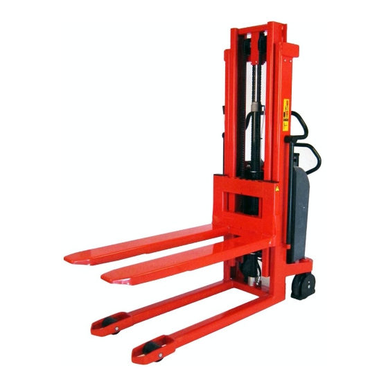
- Page 5 3.0 How to operate the Logiflex LOGIFLEX APPLICATION - PALLET HANDLING - For proper operation, stand behind the handle. Push/pull - raise/lower ELFS WHEN HANDLING CLOSED PALLETS ..USE THE STRADDLE LOGIFLEX!
-
Page 6: Optimum Safety
4.0 Optimum safety 4.1 Avoid overloads The maximum load must not be exceeded. Remember, that the Logiflex is designed for evenly distributed load, - goods on pallets etc. If the forks are point-loaded on one side, there is a risk of bending. 4.2 Avoid offset loads The load must be evenly distributed. -
Page 7: Emergency Braking
4.3 Driving loaded The Logiflex is designed for use on even and level floor. During transport the forks shall be raised as little as possible. Transport with raised forks should be made over the shortest possible distances and at low speed. 4.4 Emergency braking If it becomes necessary to use the load as a brake to prevent the Logiflex from running away, activate the DOWN button quickly, until the load reaches the ground. -
Page 8: Safety Regulations
ATTENTION MOVING PARTS Safety regulations Never walk under a raised load! Before lowering the forks, make certain that no foreign elements can hinder the free lowering of the forks. The Logiflex is designed for use on an even and level floor. During transport the forks shall be raised as little as possible. -
Page 9: Battery Specifications
5.0 There must be a current supply 5.1 Battery specifications The manufacturer offers two different battery types recommended for the electrical Logiflex Semi-trak Semi-trak Tubular cell 986034 986036 986014 Voltage 60Ah/5h 105Ah/5h 113Ah/5h Capacity 74Ah/20h 130Ah/20h 130Ah/10h Recommended for Normal use Severe daily use Life in cycles at Approx. -
Page 10: Checking The Battery
5.2 Checking the battery Method A Check the acid density in the six battery cells with an acidometer. Check each cell - max. difference between each cell 0.04 kg/l. DENSITY 1.26 - 1.28 kg/l Fully charged 1.19 - 1.20 kg/l 1/2 charged 1.16 - 1.17 kg/l 1/4 charged... -
Page 11: Fuses - Replacement
5.5 Fuses - replacement There are four fuses in the electrical circuit. 80 Amp fuse in the main supply from battery 5 Amp fuse in the control current circuit 15 Amp fuse (plug for extra equipment on the instrument board) 30 Amp fuse for built-in charger Attention! Why do the Do not insert a larger fuse;... -
Page 12: Wiring Connections
5.6 Wiring connections Many operational disturbances are caused by bad connections in the electrical circuit. Make sure that the connections are in order. Check connections regularly for damage at insulating caps or bad connections at plugs, etc. Verdigris must be removed from cable plugs. Keep all screw/nut connections tight. -
Page 13: Oil Change
6.0 Long live the Logiflex Regular inspection and the replacement of worn or defective parts in good time will prolong the life of the Logiflex. "Prevention is better than repair", therefore ensure: - Correct usage - Regular cleaning - Periodic safety inspection - Regular adjustment 6.1 Lubrication and hydraulic oil Under normal operation conditions the Logiflex requires no... -
Page 14: Fork Adjustment
6.3 Fork adjustment Two of the rollers on the fork bracket are mounted on eccentric pins, so that they can be adjusted. The adjustable rollers are at the top. 1. Loosen screw (pos. 91) (key width 5 mm). 2. Eccentric pins (pos. 56) (key width 8 mm) can now be turned to give the necessary fork adjustment. -
Page 15: Bleeding The Hydraulic System
6.5 Adjustment of steering wheel chains - Set the handle in its middle position. - Adjust the nuts (1, 2, 3 and 4) and bring the wheels into parallel. 6.6 Bleeding the hydraulic system With a load of 50-100 kg, the forks must be raised and lowered to top and bottom position 2-3 times. - Page 16 6.9 Adjustment of side play (In the mast rolls of the right side of the fork bracket) 1. Screw (A) is loosened counter-clockwise, until resistance disappears. 2. Turn the screw clockwise, until resistance appears. The following 1.5 to 2.5 turns of the screw will be a tightening of the spring (C). 3.
-
Page 17: Warranty
Control list and specifications concerning service and safety check can be ordered from Logitrans dealers. 7.5 Liability exemption The manufacturer accepts no responsibility for personal injury or material damage arising from deficiencies, defects or improper usage. - Page 18 7.0 Fault location key When the LOGIFLEX is used every day, adjustments and the replacement of worn parts might be necessary. If a fault appears during daily operation of the LOGIFLEX, first check: Oil supply Electricity supply Condition of leads and fuses If faults cannot be traced to these sources, contact your dealer, but ..
- Page 19 Cause Mending See point Oil deficiency 6.1/ 6.2 Battery discharged See point 5.3 Fuse blown See point 5.5 5Amp or 80Amp See point 5.6 Cables defective Max. load exceeded See point 4.1 Air in hydraulic system See point 6.6 Contact the Pressure relief valve incorrectly dealer adjusted...
- Page 20 Such inspection shall be performed in accordance with the instruction manual. Test instructions and test forms are available from the distributor. S 637 WWW.L .L .L .L .LOGITRANS OGITRANS OGITRANS OGITRANS.COM .COM...
Need help?
Do you have a question about the Logiflex ELF1201 and is the answer not in the manual?
Questions and answers