Table of Contents
Advertisement
Quick Links
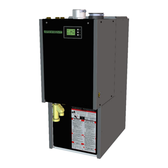
FURNACE + WATER HEATER
Installation & Operation
Manual
mOD-200
Model >
ANSI Z21.10.3 | CSA 4.3
Gas Water Heaters, Volume III Storage Water
Heaters, with Input Ratings Above 75,000 BTU per
Hour, Circulating and Instantaneous
UL 1995 | CSA C22.2 No. 236
Heating and Cooling Equipment
IMPORTANT:
•
Be sure to read these instructions and fully understand prior to
installing this product.
•
The wetted surface of this product contacted by consumable water
contains less than one quarter of one percent (0.25%) of lead by
weight.
•
After installation, keep instructions near product for future reference.
•
This product must be installed and serviced by a properly trained &
licensed professional heating contractor – FAILURE TO COMPLY
WILL VOID ALL PRODUCT WARRANTY
•
It is the responsibility of the installation contractor (upon completion
of the installation) to explain to the Owner or Operator of the heating
system how to correctly use as per these instructions and local code
requirements. Be sure that they are familiar with all heating system
equipment as well as safety devices, shut-down procedure(s) and
the need for professional service annually before the heating season
begins.
CAUTION:
•
After installation is complete it is the responsibility of the Owner or
Operator to ensure vent terminal(s) is cleared from snow, ice and/or
other debris.
syncFURNACE OD Instruction & Installation Manual – Rev 09
Combination Gas-Fired Water Heater / Central Air Fan-coil Unit
www.gradientthermal.com
Pg. 1 of 81
Advertisement
Table of Contents

Summary of Contents for Gradient syncFURNACE mOD-200
- Page 1 Combination Gas-Fired Water Heater / Central Air Fan-coil Unit FURNACE + WATER HEATER Installation & Operation Manual mOD-200 Model > ANSI Z21.10.3 | CSA 4.3 Gas Water Heaters, Volume III Storage Water Heaters, with Input Ratings Above 75,000 BTU per Hour, Circulating and Instantaneous UL 1995 | CSA C22.2 No.
- Page 2 syncFURNACE OD Instruction & Installation Manual – Rev 09 Pg. 2 of 81...
- Page 3 syncFURNACE OD Instruction & Installation Manual – Rev 09 Pg. 3 of 81...
-
Page 4: Table Of Contents
Index 1. Guideline to Symbols > ......................5 2. General and Safety Instructions > ..................6 3. Included in Packaging > ......................6 4. Regulatory & General Installation Requirements > ..............7 6. Product Information & Specifications > ................. 8 Specifications: .......................... -
Page 5: Guideline To Symbols
Clean Combustion Chamber [At Minimum, Perform Annually]: ............60 Check and Clean Condensation Line and Trap [At Minimum, Perform Semi-Annually]:......60 Flue Gas Vent & Air Intake Sealing [At Minimum, Perform Annually]: ..........61 Igniter & Flame Sensor Electrodes [At Minimum, Perform Annually]: ..........61 Burner Flame [At Minimum, Perform Annually]: ................ -
Page 6: General And Safety Instructions
2. These instructions must be kept at installation site. Additional copies are available - on request - from Gradient Thermal Inc. 3. Installation, Start-up & Service must be performed with due care and attention and must only be performed by competent, qualified, licensed and trained heating contractor(s). -
Page 7: Regulatory & General Installation Requirements
When such locations cannot be avoided, it is recommended that a suitable drain pan, adequately drained, be installed under the product. GRADIENT THERMAL INC. IS NOT LIABLE FOR ANY WATER DAMAGE. IT IS INSTALLER AND HOME OWNERS RESPOSONSIBILITY TO ENSURE ADEQUATE DRAINING IS AVAILABLE IN THE AREA ADJECENT TO THE PRODUCT. -
Page 8: Product Information & Specifications
18. The maximum allowable ambient temperature of the room where this product will be installed is 104°F (40°C). 19. Suggested list of codes and standards for the United States and Canada - a. General Installation: - Installation of Air Conditioning and Ventilation Systems NFPA 91 (latest edition). b. - Page 9 IN THE STATE OF MASSACHUSETTS ONLY (a) For all side-wall vented gas fueled equipment installed in every dwelling, building or structure used in whole or in part for residential purposes, including those owned or operated by the Commonwealth and where the side-wall exhaust vent termination is less than seven (7) feet (2.14m) above finished grade in the area of the venting, including but not limited to decks and porches, the following requirements shall be satisfied: 1.
-
Page 10: Specifications
SPECIFICATIONS: Low Velocity / Normal Static Duct High Velocity / High Static Duct Physical Weight 40.5 x 40.5 x 40.5 x 44.5 x 44.5 x 40.5 x 30 40.5 x 37 40.5 x 30 Dimensions [H x L x W] x 17.5 x 17.5 x 17.5... -
Page 11: Model Number Identification
MODEL NUMBER IDENTIFICATION: mOD-200-N-14LEN1 Hydronic Configuration 1 = 1 supply & return, w_ re-circ Model Name 2 = 1 supply & return, w_ re-circ & fc bypass 3 = 1 supply & return, w_o re-circ mOD = Integrated, Modulati ng Gas-Fired Ins tantaneous Water Heat er &... -
Page 12: Dimensions And Connection Descriptions
7. DIMENSIONS AND CONNECTION DESCRIPTIONS > syncFURNACE OD Instruction & Installation Manual – Rev 09 Pg. 12 of 81... - Page 13 Location Location Thread Pipe Connection ↔ ↕ Xref Yref Specification Inc h Inc h A - INTERNA L P RV TO DRA IN 3/4" NP T FEM A LE 6.44 1 63 4.41 1 1 2 B - CONDENSA TE TO DRA IN 7/8"...
- Page 14 mOD-200-15H syncFURNACE OD Instruction & Installation Manual – Rev 09 Pg. 14 of 81...
- Page 15 mOD-200-18H syncFURNACE OD Instruction & Installation Manual – Rev 09 Pg. 15 of 81...
-
Page 16: Installation
8. INSTALLATION > MINIMUM CLEARANCES: Front Back Sides Bottom Vent Pipe Clearance Requiements Inch Inch Inch Inch Inch Inch Minimum Recommended for Service 25.4 Note: 1. It is highly suggested that Recommended for Service minimum clearance requirements are maintained to ensure straight forward access for future product service / maintenance. 2. -
Page 17: General Venting
GENERAL VENTING: syncFURNACE OD utilizes a modulating gas power burner and incorporates a sealed combustion venting design. This product requires a “Special Venting System” designed for pressurized venting. syncFURNACE OD is suitable for use for sidewall (horizontal) and vertical venting using field supplied venting materials. -
Page 18: Acceptable Vent Configurations
DO NOT locate product in areas where high levels of install operate dust or humidity are present syncFURNACE during CAUTION construction - will cause heavy suiting burner heat DO NOT operate product in exchanger fouling. an area that is under construction or renovation. - Page 19 All vent and air-inlet materials installed on gas fired appliances in Canada or the United States must meet the standards listed in the above Acceptable Vent WARNING Materials Table. Failure to comply could result in fire, serious injury or death. The use of cellular core PVC (ASTM F891), cellular core CPVC, or Radel®...
- Page 20 Notes: 1. syncFURNACE OD is supplied with 3” Flue Gas and Combustion Air vent connections. If reducing to 2”, make transition as soon as possible. 2. Minimum acceptable equivalent vent length is 5 feet (1.53m) for 2” diameter materials and 8 feet (2.44m) for 3”...
-
Page 21: Room Dependent Combustion Air Supply
It is the installer’s responsibility to familiarize themselves with the hazards associated with explosive cements and primers and to take all precautions necessary to reduce these risks. Failure to follow these instructions can cause explosions, property damage, injury or death. Only use solvents &... -
Page 22: Connecting Vent Pipe To Syncfurnace Od
CONNECTING VENT PIPE TO SYNCFURNACE OD: 1. The installation of a swing joint is highly recommended to attain slope in horizontal runs in the Flue Gas Venting system. (For both Direct Vent and Room Dependent Combustion Air Supply installations). 2. DO NOT apply primer or cement to the pipe ends that are inserted into the syncFURNACE OD connections - Use gear clamps to secure vent connections in place after insertion. -
Page 23: Venting Termination Options
VENTING TERMINATION OPTIONS: Notes: 1. Above termination options may be substituted with an approved vent kit listed in the table. 2. Flashings and storm collars are field supplied. Flashings and storm collars suitable for B-vent materials (or better) may be used. It is the responsibility of the installer to include flashings and seal penetrations for the venting system. - Page 24 12. At termination point, install vent screens into the last opening for both the Flue Gas Outlet and Combustion Air Inlet fittings. 13. For sidewall terminations - if additional rigidity is required, secure Combustion Air Inlet and Flue Gas Outlet piping to external wall. 14.
- Page 25 In addition to preventing ingestion of chemical contaminants, care must be taken to ensure air intake terminals are not installed in locations where WARNING contamination might occur due to ingestion of particulate foreign material (dust, dirt, debris etc.). Insulation should not be used on non-metal (PVC, CPVC, Polypropylene) venting materials.
-
Page 26: Venting Termination Clearances
VENTING TERMINATION CLEARANCES: For installations in Canada, vent terminations must follow the requirements of Local and National Codes – CAN/CSA B149.1 or 2. For installations in the United States of America, vent terminations must follow the requirements of Local and National Codes – ANSI Z223.1 or NFPA 54 In Canada and the USA the Combustion Air Inlet termination MUST NOT be –... -
Page 27: Mandatory Venting Pre-Fire Procedure
MANDATORY VENTING PRE-FIRE PROCEDURE: Do not apply power to syncFURNACE OD prior to performing the mandatory WARNING venting pre-fire procedure for plastic venting. This procedure is required for IPEX venting materials that are assembled using solvents and cements. Once the venting system has been fully assembled follow these steps: 1. -
Page 28: Condensation Trap
CONDENSATION TRAP: To achieve maximum operating efficiency, flue gases inside the heat exchanger and chimney will condense during burner operation. It is critical that the venting system be installed in accordance with the requirements of this manual so that condensate properly drains back into the heat exchanger and out the side discharge. - Page 29 & heat exchanger will need to be inspected and cleaned. The internal refractory, gaskets, flame sensor & direct spark igniter may need to be replaced with Certified Replacement Parts from Gradient Thermal Inc. Failure to properly inspect and repair will result in dangerous water heater operation resulting in property damage, fire or loss of life.
-
Page 30: Gas Line Connection
GAS LINE CONNECTION: Gas-line sizing and the connection to syncFURNACE OD must be made in accordance with current edition of codes CAN/CSA B149.1 or .2, or National Fuel Gas Code ANSI Z223.1/NFPA 54, as well as local codes where applicable. All gas piping and connections must be completed by a qualified gas-fitter. Install gas-line with a manual shut-off valve (listed by a nationally recognized testing lab) and 3”... -
Page 31: Plumbing Syncfurnace Od
PLUMBING SYNCFURNACE OD: syncFURNACE OD is approved for combination water (Potable) heating and space heating applications. It incorporates an internal pump that circulates fluid through the internal water heating coil (to provide furnace heating), and (for re-circ models) through an external hot water pre-heat re-circulation line, the switching between these 2 functions is internally managed through controlled of a 3-way diverver valve. - Page 32 DO NOT install an isolation valve in-line with the PRV to Drain line. The discharge pipe for the pressure relief valve must be orientated to prevent scalding of attendants. Pipe pressure relief valve discharge pipe close to the floor – follow the requirements of the local and national codes.
- Page 33 PLUMBING SETUP - syncFURNACE OD Instruction & Installation Manual – Rev 09 Pg. 33 of 81...
- Page 34 syncFURNACE OD Instruction & Installation Manual – Rev 09 Pg. 34 of 81...
- Page 35 HVAC duct system. The fan-coil system has been optimized by Gradient to maximize efficiency and output leading heating capacity with lower supply water temperatures. An optional outdoor sensor can be utilized to vary (reset) the heating coil supply water temperature based on outdoor tempertarure, this further increases efficiency of the system and comfort for home owners.
-
Page 36: Water Supply Quality Requirements
WATER SUPPLY QUALITY REQUIREMENTS: 1. Proper maintenance of the appliance is required to ensure water meets EPA quality standards. 2. Maximum contaminant levels allowed, based on EPA National Secondary Drinking Water Regulations (40 CFR Part 143.3): Contaminant Maximum Allowable Level Total Hardness Up to 150 mg/l (8 grains / gallon) Free Carbon Dioxide (CO2) -
Page 37: Purging Air From Syncfurnace Od
PURGING AIR FROM SYNCFURNACE OD: Ensure Main Power to syncFURNACE OD is turned OFF! Ensure external piping system is complete and inspected for leaks. Open isolation valves to allow water to fill into syncFURNACE OD. Allow system to fill for several minutes. Once system is pressurized, open manual air bleeder at top of fan-coil to bleed air and water from the internal piping. -
Page 38: Connecting Control (Low-Voltage) Wiring
CONNECTING CONTROL (LOW-VOLTAGE) WIRING: Ensure the main supply power to syncFURNACE is turned OFF whenever the control wiring panel is removed. Under any circumstance is there ever a need to apply an external power source to any of the low-voltage connection terminals. - Page 39 Low Voltage Terminals: Low Voltage Wire Terminals Terminal Description Neutral for Control 24Vac - Wire to thermostat for power Control 24Vac Hot - Wire to thermostat, power supply for W,R,G,Y1,Y2 demands Wire to thermostat - When energized provides signal to syncFURANCE for Warm-air heating demand Wire to thermostat - When energized provides signal to syncFURANCE for Fan-circulation demand...
-
Page 40: Connecting Main Power (115Vac) Wiring
10°F below the switch set-point point. The other limit switch is located in the water heater jacket and is not resettable. If this switch opens, contact Gradient Thermal Inc. for service and support. These switches are included in the product to prevent excessive overheating. DO NOT TAMPER WITH THE WIRING OR POSITION OF THESE SWITCHES. - Page 41 Electric Shock Hazard. Can cause injury or death. Before attempting to perform any service or maintenance, turn the electrical power to unit OFF at externally installed service switch. FOR ALL FIELD WIRING: USE ONLY COPPER CONDUCTOR SUPPLY WIRE SUITABLE FOR 105°C (221°F) syncFURNACE OD Instruction &...
-
Page 42: Fan-Coil Installation
FAN-COIL INSTALLATION: General Requirements: 1. syncFURNACE OD fan-coil installation must conform to local building codes. 2. syncFURNACE OD can only be installed in up-flow installation types. 3. It is highly recommended to install so that the bottom front panel is easily accessible after installation for future maintenance and service of the blower. - Page 43 Return Air Duct Options: 17.5” wide product versions (05L / 10L / 06H, 14L / 10H): All other product versions: syncFURNACE OD Instruction & Installation Manual – Rev 09 Pg. 43 of 81...
- Page 44 NOTE Duct Distribution Guide: Duct joints shall be, as a rule, sealed to prevent leakage of air which may cause objectionable sound & in-efficient operation. Round ducts (supply side) are more rigid and reduce air restriction. If concerns about noise are not a factor, duct runs could be sized according to the smallest permissible duct diameter which would be governed only by the available external static...
-
Page 45: Control Setup
CONTROL SETUP: syncFURNACE OD has an advanced internal control platform that incorporates custom operating logic specifically designed for optimizing prioritization and functionality related to combined domestic water and fan-coil space heating. Built-in priority logic is included which enables automatic switch-over to domestic water heating anytime incoming domestic water flow is sensed. - Page 46 DEMAND TYPES: These demands are displayed at the top left on the display. The demand will only show if there is a trigger calling for the demand. Demand Types Displayed on Description of Demand Controller Dom estic Hot Water FC_W Fan-coil Heating (W) RECIRC Dom estic Hot Water Re-circ...
- Page 47 NAVIGATING THE CONTROLLER: To cycle through the different main boiler information screens and access to the syncFURNACE SETUP MENU is achieved by using the three buttons (and combination thereof) located to the right of the control screen. (UP) button is used to scroll up through the main boiler information screens, scroll up in syncFURNACE SETUP MENU screens and increase...
- Page 48 SETUP MENU: syncFURNACE OD SETUP MENU is used for configuration of zone applications, adjusting the design values, burner combustion testing options, commissioning options and remote monitoring setup. To access the SETUP MENU push and hold SET for 10 seconds. Use the UP or DOWN buttons to scroll through the various settings.
- Page 49 ZONE SETU P Fan Coil 1) DHW - Allows adjustment of the fan-coil blower speeds for each HVAC function (ie. Heating (W), 2) FAN-COIL air-circ (G), cooling 1 (Y1), cooling 2 (Y2) 3) DHW RECIRC - Customization of fan-coil heating water set-point parameters 4) ZONE 4 5) RESTORE DEFAULTS FAN COIL Setup...
- Page 50 DHW RECIRC ZONE SETU P - Allows user to enable / disable DHW recirculation pump. 1) DHW - When enabled hot water will be circulated through recirc piping in building and back to unit. 2) FAN-COIL - Requires recirc piping to be connected on recirc fitting at bottom of unit. 3) DHW RECIRC - When enabled, internal pump &...
- Page 51 SETUP MENU Burner Setup 1) ZONE SETUP - Used to force burner to operate at MAXIMUM, MINIMUM or IGNITION burner input rate to 2) BURNER SETUP perform gas valve calibration and/or combustion analysis of burner system. 3) COMMISSIONING 4) STATISTICS 5) REMOTE MONITORING Burner Setup Combustion Blower Override...
-
Page 52: Commissioning
9. COMMISSIONING > Before placing the product into operation ensure; CHECK 1. Venting system is completely assembled and seal tested. Ensure venting system meets the requirements of the Venting Installation sections in this manual. Ensure the pre-fire venting procedure has been completed. Confirm that venting system is not shared with any other gas burner appliance in the home. -
Page 53: Testing Gas Inlet Pressure
TESTING GAS INLET PRESSURE: Both static and running gas pressure needs to be tested prior to operating syncFURNACE OD. Check the rating plate on syncFURNACE OD to ensure it is configured for the fuel type you are using. To measure static pressure: 1. - Page 54 Testing Gas Inlet Pressure (Con’t): For your safety read before operating - It is the responsibility of the installing contractor to ensure that all controls are operating properly when the installation is completed. Set temperature control to the WARNING desired temperature and cycle the product several times to ensure proper operation of product.
- Page 55 syncFURNACE OD Instruction & Installation Manual – Rev 09 Pg. 55 of 81...
- Page 56 Testing Gas Inlet Pressure (Con’t): A CO Measurement must be taken before and after working on the water heater to eliminate risks to health and to guarantee the performance of the system. Ensure CO reading is less than 180 ppm @ MAX input. If CO is > 180 ppm follow the Combustion setting instructions to reduce reading.
-
Page 57: Testing Combustion
TESTING COMBUSTION: syncFURNACE OD has a pre-mix modulating gas burner combustion system. It uses a negative pressure gas-valve that is pre-set and calibrated at factory for optimized water heater performance. During a demand for heat, the syncFURNACE OD controller uses the target supply water temperature for the demand and modulates burner energy input (between Maximum and Minimum Input Rating) into the water heater to only provide the required energy so the actual water temperature equals the supply water temperature target. - Page 58 7. If values are within the range in the table turn-off heat demand, insert plug back into Combustion Analyzer Measurement Port and return syncFURNACE OD back to normal operating condition – ensure that “BURNER ORIDE” is set to “OFF”. There is no need to continue on to step 8. If combustion readings are outside the acceptable range continue to step 8.
-
Page 59: Maintenance & Service
10. MAINTENANCE & SERVICE > The building owner is responsible for keeping the Flue Gas Outlet and Combustion Air Inlet terminations free from snow, ice, or other potential blockages and for scheduling water heater maintenance and service as described in this section. FAILURE TO PROPERLY MAINTAIN THIS PRODUCT MAY RESULT IN SERIOUS INJURY OR DEATH. -
Page 60: Clean Combustion Chamber [At Minimum, Perform Annually]
CLEAN COMBUSTION CHAMBER [AT MINIMUM, PERFORM ANNUALLY]: 1. With burner still removed, inspect internal surfaces of combustion chamber. 2. Vacuum inside combustion chamber using a vacuum with nylon brush and high-efficiency filter. 3. Inspect the condition of the insulation disc at the back of the combustion chamber. Cover it to protect it from being damaged or becoming wet during the cleaning process. -
Page 61: Flue Gas Vent & Air Intake Sealing [At Minimum, Perform Annually]
FLUE GAS VENT & AIR INTAKE SEALING [AT MINIMUM, PERFORM ANNUALLY]: 1. Using Flat-head screw driver, ensure worm-gear clamps are tight that connect the gas-valve air supply shroud to the combustion air supply tube. 2. Inspect the Combustion Air intake line, both inside the appliance and outside to ensure no leaks or worn parts are present. -
Page 62: Troubleshooting
Condensate Trap Pressure Switch – Undersized drain or partial or full trap blockage 2. Corrective action for limit switch – a. Vent Limit Switch – Contact Service/Repair Contractor & Gradient Thermal Inc. ALM 3 b. Water Supply Hi-Limit Switch –... - Page 63 Code # Corrective Action 1. Verify gas shut-off valve is open 2. Verify gas line is at correct pressure 3. Verify gas valve test ports are closed 4. Verify differential pressure tube (at gas valve) is connected from port on combustion air intake pipe to governor port on gas valve 5.
- Page 64 1. Check water heater cold water supply and ensure operation within safe operating characteristics and pressure limits. 2. Ensure all valves are open and that water is able to enter and fill the system piping. 3. Check filters and/or dirt strainers and ensure no blockage. If blockage exists, clean. 4.
-
Page 65: Appendix A: Internal Wiring Diagram
APPENDIX A: INTERNAL WIRING DIAGRAM > syncFURNACE OD Instruction & Installation Manual – Rev 09 Pg. 65 of 81... -
Page 66: Appendix B: Sequence Of Events
APPENDIX B: SEQUENCE OF EVENTS > syncFURNACE OD Instruction & Installation Manual – Rev 09 Pg. 66 of 81... -
Page 67: Appendix C: Replacement Parts List
APPENDIX C: REPLACEMENT PARTS LIST > syncFURANCE OD Replacement Parts List - Shown Order Item No. Component Description Part No. HEAT EXCHANGER ASSY 111156 VERSION > mOD-200 PRES & SUPPLY TEMP SENSOR 110939 ASSY SUPPLY HI-LIMIT SAFETY 110146 SWITCH RETURN TEMP SENSOR 110778 3in1 FLUE GAS OUTLET FITTING 110949... - Page 68 syncFURANCE OD Replacement Parts List - Shown Order Item No. Component Description Part No. WARM-AIR HEATING COIL > 17.5” 111242 WIDE, 30” DEEP MODELS WARM-AIR HEATING COIL > 17.5” 110931 WIDE, 37” DEEP MODELS WARM-AIR HEATING COIL > 21” 110932 WIDE MODELS WARM-AIR HEATING COIL >...
-
Page 69: Appendix D: Handling Instructions For Refractory Cement Fibers (Rfc)
APPENDIX D: HANDLING INSTRUCTIONS FOR REFRACTORY CEMENT FIBERS (RFC) > Reduce the Risk of Exposure Precautions and Recommended Personal Protective Equipment Avoid contact with skin and eyes • Wear long-sleeved clothing, gloves and safety goggles or glasses. Avoid breathing in silica dust •... -
Page 70: Appendix E: Annual Inspection & Maintenance Record
APPENDIX E: ANNUAL INSPECTION & MAINTENANCE RECORD > Required Inspection-points @ Installation Year 2 Year 3 Year 4 Year 5 Dat e: Dat e: Dat e: Dat e: Dat e: Inspect the general condition of the heating system & its components Test functions of all the demands wired into the product 3 C heck gas system for leaks... - Page 71 Required Inspection-points Year 6 Year 7 Year 8 Year 9 Year 10 Dat e: Dat e: Dat e: Dat e: Dat e: Inspect the general condition of the heating system & its components Test functions of all the demands wired into the product 3 C heck gas system for leaks 4 C heck plumbing system for leaks Verify product chasis ground...
-
Page 72: Appendix F: Internal Pump Specifications
APPENDIX F: INTERNAL PUMP SPECIFICATIONS > Pump Performance Curve - Grundfos UPS-15-78 Speed 3 Speed 2 Speed 1 11.5 16.3 Flow Rate (GPM) Grundfos UPS 15-78 PUMP PERFORMANCE - Speed 3 Setting Flow Rate (GPM) 11.5 16.3 Head Loss @ Flow (ft head) 32.6 30.8 28.6... -
Page 73: Appendix G: Heat Exchanger Specification
APPENDIX G: HEAT EXCHANGER SPECIFICATION > Water Heater Head Loss Curve 200 Model Flow Rate (GPM) Water Heater Head Loss - 200 MODEL Flow Rate (GPM) Head Loss @ Flow (ft head) 15.0 22.0 30.0 40.0 51.0 65.0 80.0 Head Loss @ Flow (psi) 13.0 17.3 22.1... -
Page 74: Appendix H: Fan-Coil Performance
APPENDIX H: FAN-COIL PERFORMANCE > 5L MODEL: 300 CFM 400 CFM 500 CFM 600 CFM 3200 3000 2800 2600 2400 2200 2000 1800 1600 1400 1200 1000 DUCT SYSTEM ESP RPM SETTING TABLE Duct System ESP [inch w.c.] 300 CFM 1625 1738 1851... -
Page 75: Model
10L MODEL: 400 CFM 600 CFM 800 CFM 1000 CFM 1200 1100 1000 DUCT SYSTEM ESP RPM SETTING TABLE Duct System ESP [inch w.c.] 400 CFM 600 CFM 800 CFM 1017 1000 CFM 1023 1066 1110 FC HEAT OUTPUT [BTU/hr] FC SUPPLY AIR TEMP [°F] Heating Coil Supply Water Temp Heating Coil Supply Water Temp... -
Page 76: Model
14L MODEL: 800 CFM 1000 CFM 1200 CFM 1400 CFM 1200 1100 1000 DUCT SYSTEM ESP RPM SETTING TABLE Duct System ESP [inch w.c.] 800 CFM 1000 CFM 1200 CFM 1009 1400 CFM 1036 1077 FC HEAT OUTPUT [BTU/hr] FC SUPPLY AIR TEMP [°F] Heating Coil Supply Water Temp Heating Coil Supply Water Temp 90 °F... -
Page 77: Model
18L MODEL: 900 CFM 1200 CFM 1500 CFM 1800 CFM 1300 1200 1100 1000 DUCT SYSTEM ESP RPM SETTING TABLE Duct System ESP [inch w.c.] 900 CFM 1200 CFM 1500 CFM 1014 1054 1800 CFM 1018 1057 1095 1132 1169 FC HEAT OUTPUT [BTU/hr] FC SUPPLY AIR TEMP [°F] Heating Coil Supply Water Temp... -
Page 78: Model
22L MODEL: 1000 CFM 1400 CFM 1800 CFM 2200 CFM 1400 1300 1200 1100 1000 DUCT SYSTEM ESP RPM SETTING TABLE Duct System ESP [inch w.c.] 1000 CFM 1400 CFM 1800 CFM 1000 1070 1130 2200 CFM 1010 1100 1170 1220 1260 FC HEAT OUTPUT [BTU/hr]... -
Page 79: Appendix I: Temporary Construction Heat
APPENDIX I: TEMPORARY CONSTRUCTION HEAT > This application won’t void product warranty, but the below requirements need to be followed for it to be ok for use - syncFURNACE may be used for temporary heating of buildings or structures under construction only when the following conditions have been met: b. -
Page 80: Appendix I: Example Humidifier Wiring Diagram
!! All Components are Field Supplied !! Typical Home Thermostat !! DO NOT APPLY EXTERNAL VOLTAGE TO ANY OF THESE WIRES !! Gradient Controller – TOP VIEW Rev: 01 syncFURNACE OD Instruction & Installation Manual – Rev 09 Pg. 80 of 81... - Page 81 Disclaimer Gradient Thermal Inc. shall not be responsible for errors in its brochures or printed materials. Gradient Thermal Inc. reserves the right to alter its products at any time without notice, provided that alterations to products already on order shall not require material changes in specifications previously agreed upon by Gradient Thermal Inc.
Need help?
Do you have a question about the syncFURNACE mOD-200 and is the answer not in the manual?
Questions and answers