Table of Contents
Advertisement
Advertisement
Table of Contents

Related Manuals for ThyssenKrupp TW160


Summary of Contents for ThyssenKrupp TW160
- Page 1 Operating manual TW160 drive thyssenkrupp Aufzugswerke...
- Page 2 Choice of colours The choice of colours used in our documents for the components is solely for illustration purposes in the documentation. Contact your thyssenkrupp Aufzugswerke sales partner for details of colours for your specific products. Form of address To improve readability, a gender-specific form of address has not been used. Gender-specific pronouns therefore refer to both men and women.
-
Page 3: Table Of Contents
Operating manual Table of Contents TW160 drive Table of Contents About these instructions ........... 7 Guide to layout ................7 Safety .................. 8 Warning notes ................. 8 Safety requirements ................ 9 Warranty and liability ..............10 Dangers in handling the product ............11 International occupational health and safety regulations ....12... - Page 4 Operating manual Table of Contents TW160 drive Installation ................ 56 Setting up the machine base frame ..........56 Aligning the machine ..............56 Installation (frame with rope pulley) ..........57 Mounting the rope guard ..............59 Mounting the rope guard complying with EN81-77 ......60 Mounting the shift protection complying with EN81-77 ....61...
- Page 5 Operating manual Table of Contents TW160 drive 10.6 Manufacturer specifications for Bernstein switch ......105 10.7 Details regarding ABV, ESV, EU-BD as well as shaft calculations ..................111 thyssenkrupp Aufzugswerke Version 03/2019...
-
Page 7: About These Instructions
Operating manual About these instructions TW160 drive About these instructions Guide to layout Sequence of actions involving several steps First action. Second action. Interim result (optional) Third action. Final action step with end marker. Result of action (optional) Course of action with independent steps ... -
Page 8: Safety
Operating manual Safety TW160 drive Safety Warning notes Warning notes are intended for the protection of persons and property. Warning notes must be read and observed by every person who works on the product. Warning notes precede activities that pose a hazard for people and the product. -
Page 9: Safety Requirements
Operating manual Safety TW160 drive Safety requirements This document contains important information for safe operation of the product. Keep this document and all other applicable documents at the location of use for the entire working life of the product. -
Page 10: Warranty And Liability
Any other or additional form of use shall be regarded as non-compliant with the intended use. thyssenkrupp Aufzugswerke GmbH shall not be liable for any damage arising from such use and any damage arising due to operator errors. -
Page 11: Dangers In Handling The Product
TW160 drive Dangers in handling the product The traction sheave and handwinding wheel of the TW160 are designed without safety covers. This means that the drive may only be operated in a closed room. It must be ensured when persons are in the vicinity of the machine that there is adequate safety clearance to all revolving parts (marked in yellow). -
Page 12: International Occupational Health And Safety Regulations
Operating manual Safety TW160 drive International occupational health and safety regulations Table 2.5-1 International rules for occupational health and safety can also be found in various languages on our ELI web platform and can be downloaded at: http://www.thyssenkrupp-elevator-eli.de/nc/de/downloads.html thyssenkrupp Aufzugswerke... -
Page 13: Personal Protective Equipment
Operating manual Safety TW160 drive Personal protective equipment Danger Cause (examples) Risks Remedy Equipment Unprotected shaft Fall Safety harness WARNING: Do not walk underneath suspended loads! Head Falling tool Head injury protection Transport of heavy load Sharp-pointed objects... -
Page 14: Product Description
TW160 drive Product Description Standards and legal requirements EN81-1:2010-06 and EN81-20/50 The TW160 machines comply with the European standard EN81-1:2010-06 and EN81-20/50 The drive is part of the protection device according to DIN EN81-1:2010-06 / 9.11 and EN81-20/50/5.6.7. thyssenkrupp Aufzugswerke... -
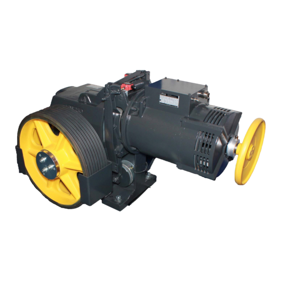
Page 15: Description
Operating manual Product Description TW160 drive Description 3.2.1 Standard version thyssenkrupp Aufzugswerke Version 03/2019... -
Page 16: Version With Emergency Brake - Nbs
Operating manual Product Description TW160 drive Item Designation Item Designation Traction sheave (standard Driving gear version) Motor (version V3F, frequency Operational brake controller) Actual-value sensor (type Handwinding wheel WDG100) Rope guard (adjustable) Oil drain (3/4") Oil level monitor (dipstick) and... -
Page 17: Version For Traction Sheave In The Shaft Sa9
Version for traction sheave in the shaft SA9 TW160_23001_GER Item Designation Item Designation Traction sheave shaft, SA4/9 TW160 machine SA9 version External bearing (bearing housing with self-aligning bearing on Traction sheave, SA4/9 version adapter sleeve) Compensating support (for Mounting surfaces for machine... -
Page 18: Version For Vapour-Proof Partition Wall Sa4
External bearing (bearing housing with self-aligning bearing on Traction sheave, SA4/9 version adapter sleeve) Compensating support (for Mounting surfaces for machine statically defined machine base frame mounting) Partition wall with seal for TW160 machine base frame SA4 Fig. 3.5-1 thyssenkrupp Aufzugswerke Version 03/2019... -
Page 19: Special Versions Sa2 / Sa3 / Sa3.1 / Sa11 / Sa12/Sa15
Operating manual Product Description TW160 drive Special versions SA2 / SA3 / SA3.1 / SA11 / SA12/SA15 Item Designation Item Designation Brake monitoring SA3 / 3.1 and/or Handwinding wheel, on gear side brake test switches for SA15 - SA2 Additional terminal box - SA12 for... -
Page 20: Version With Safeguard Measures Complying With En81-77
For manual operation, a brake release lever is fitted. Gear housing The TW160 has a monobloc housing with two fitted and screw-connected bearing brackets. The motor flange is cast onto the housing. The right-hand or left-hand version of the traction sheave is created with the corresponding installation of the bearing brackets in the housing. - Page 21 Operating manual Product Description TW160 drive Drive motor Flange-mounted type B9 and IMB5 three-phase motors are used. The motor shaft-worm shaft connection is established in the type B9 versions using a bolted rigid coupling and in the type IMB5 versions using a flexible coupling.
-
Page 22: Technology
Operating manual Technology TW160 drive Technology Technical data name unit technical data manufacturer ThyssenKrupp Elevator gear type TW160 axle distance ratios 50:1 / 42:1 / 35:1 / 57:2 / 51:2 / 45:2 / 41:3 oil filling approx. 16.5 synthetic gear oil... - Page 23 Operating manual Technology TW160 drive Designation Unit Mass moment of inertia J [kgm Flywheel rim 0.285 0,458 0.533 0,600 0.758 0,900 1,070 1.435 1,750 2,280 Flywheel rim kgm2 0.057 0.057 0.057 Total 0,342 0,515 0,590 0,657 0,815 0,957 1,127 1,492 1,807 2,337 TW63_30707_ENG Table 4.1-2...
- Page 24 Operating manual Technology TW160 drive thyssenkrupp Aufzugswerke Version 03/2019...
- Page 25 Operating manual Technology TW160 drive 4.1.4 Emergency brake More detailed information as well as technical information for setting up and operation of machines with NBS emergency brake can be found in a separate operating manual. These are delivered with drives with emergency brake system equipment.
- Page 26 TW160 drive 4.1.6 Weight data machine version name unit weight without motor with motor DTE180 ZB machine TW160 accessories for SA9 accessories for NBS 2), 3) traction sheave D720 motor DTE180 ZB machine complete 1075 without motor weight for traction sheave D640 approx. 140 kg and D800 approx. 190 kg...
-
Page 27: Dimensions Of Machine
Operating manual Technology TW160 drive Dimensions of machine 4.2.1 Standard version Item Designation Item Designation Pictured: traction sheave position Additionally for SA1 right / left mirror-inverted to A-A Fig. 4.2-1 thyssenkrupp Aufzugswerke Version 03/2019... - Page 28 Operating manual Technology TW160 drive 4.2.2 Version with emergency brake - NBS Fig. 4.2-2 thyssenkrupp Aufzugswerke Version 03/2019...
- Page 29 Operating manual Technology TW160 drive 4.2.3 Version for traction sheave in the shaft (SA9) Item Designation Item Designation Centre, rolling bearing Centre, bearing housing Fig. 4.2-3 thyssenkrupp Aufzugswerke Version 03/2019...
- Page 30 Operating manual Technology TW160 drive 4.2.4 Version for vapour-proof partition wall SA4 (Partial Ex) Item Designation Item Designation Centre, rolling bearing Centre, bearing housing Fig. 4.2-4 thyssenkrupp Aufzugswerke Version 03/2019...
-
Page 31: Type Plate
Operating manual Technology TW160 drive 4.2.5 Special versions SA2/SA11/SA12 Fig. 4.2-5 Type plate The current type and the technical data are specified on the type plate of the product. Motor data The technical data can be found on the type plate. - Page 32 Technology TW160 drive 4.5.1 Assembly, machine base frame TW160 - 62 340 01 10 0 Machine base frame version without rope pulley for use in: Installations with 1:1 rope suspension and direct rope departure for an elevator car - counterweight rope distance ASL (DT + 100) mm depending on the traction sheave diameter ...
- Page 33 Technology TW160 drive 4.5.2 Assembly, machine base frame TW160 - 62 340 02 10 0 Machine base frame in version with rope pulley on supports depending on the pulley hub position in left-hand or right-hand configuration for use with: Installations with 1:1 rope suspension and elevator car - counterweight rope distance ASL = 795 ...
- Page 34 Project planning dimensions, see dimension sheet 4.5.3 Assembly, machine base frame TW160 - 62 340 03 10 0 Machine base frame version with rope pulley on concrete foundations - depending on whether the rope pulley position is on the left or right for use in: ...
- Page 35 Operating manual Technology TW160 drive TW160_31011_GER Item Designation Item Designation Machine TW160 Machine base frame Pedestal bearing for rope pulley Rope pulley Foundations (supplied by Rope pulley customer) Insulation elements Fig. 4.5-3 The complete machine base frame comprises the following components: ...
- Page 36 Operating manual Technology TW160 drive Technical data Weight of machine base frame rope pulley version [mm] weight incl. rope pulley D450 D540 D640 TW160_31008_ENG Table 4.5-2 Project planning dimensions Project planning dimensions, see dimension sheet thyssenkrupp Aufzugswerke Version 03/2019...
- Page 37 Technology TW160 drive 4.5.4 Assembly, machine base frame TW160 - 62 340 04 10 0 Machine base frame for "Partial Ex" installations with vapour-proof wall duct (SA4) in a version without a rope pulley for use in: Installations with 1:1 rope suspension and direct rope departure for an elevator car - counterweight rope distance ASL ...
- Page 38 A reinforced mounting (6 x M20-8.8 / 2 x M16-8.8) is used (assembly, mounting parts 62 340 03 98 0) is used for individual applications of the TW160 machine with horizontal or vertically upward rope departure - except for the special versions SA4/9.
- Page 39 Operating manual Technology TW160 drive 4.5.6 Version with earthquake safeguard complying with EN81-77 Optional components are available for the TW160 O SR and TW160 M SR base frames; these meet the requirements for protection devices complying with EN81-77. Item Designation Item...
- Page 40 Item Designation Item Designation Shift protection complying with TW160 M SR machine base EN81-77 frame Fig. 4.5-7 In the case of deployment of the machine in earthquake categories 2 and 3, additional safeguard measures in accordance with EN81-77 are necessary.
-
Page 41: Machine Base Frame Dimension Sheets
Operating manual Technology TW160 drive Machine base frame dimension sheets 4.6.1 Version without rope pulley Item Designation Item Designation Machine with traction sheave Machine with traction sheave position - left position - right Centre of gravity Fig. 4.6-1 thyssenkrupp Aufzugswerke... - Page 42 Operating manual Technology TW160 drive Project planning dimensions: Project planning dimension L dependent on traction sheave diameter DT and traction sheave position - left or right - of the machine. project planning dimension L unit traction sheave position traction sheave version...
- Page 43 Operating manual Technology TW160 drive 4.6.2 Version with rope pulley / machine base frame with supports Version with rope pulley position on left TW160_31102_GER Item Designation Item Designation With rope pulley D540 With rope pulley D640 Machine with traction sheave...
- Page 44 Operating manual Technology TW160 drive Version with rope pulley position on right TW160_31103_GER Item Designation Item Designation With rope pulley D540 With rope pulley D640 Machine with traction sheave With rope pulley D450 position - left Machine with traction sheave...
- Page 45 Operating manual Technology TW160 drive Project planning dimensions Project planning dimension L dependent on traction sheave diameter DT and traction sheave position - left or right - of the machine traction sheave version rope distance elevator car - counterweight 1400 TW160_31005_ENG Table 4.6-3...
- Page 46 Operating manual Technology TW160 drive 4.6.3 Version with rope pulley / machine base frame on concrete foundation Version with rope pulley position on left TW160_31104_GER Item Designation Item Designation With rope pulley D540 With rope pulley D640 Machine with traction sheave...
- Page 47 Operating manual Technology TW160 drive Version with rope pulley position on right TW160_31105_GER Item Designation Item Designation With rope pulley D540 With rope pulley D640 Machine with traction sheave With rope pulley D450 position - left Machine with traction sheave...
- Page 48 Operating manual Technology TW160 drive Project planning dimensions Project planning dimension L dependent on traction sheave diameter DT and traction sheave position - left or right - of the machine traction sheave version rope distance elevator car - counterweight...
- Page 49 Operating manual Technology TW160 drive 4.6.4 Version with vapour-proof partition wall (SA4) Item Designation Item Designation Machine with traction sheave Machine with traction sheave position - left position - right Centre of gravity Fig. 4.6-6 thyssenkrupp Aufzugswerke Version 03/2019...
-
Page 50: Encoder
The installation and connection are described in external operating Chapter 10 manual in the Appendix Encoders are distinguished by type depending on the control system deployed. The following encoders are available for the TW160. Encoder type Pulses 1024 tkAW inverters and third-party inverters... -
Page 51: Transportation And Storage
Operating manual Transportation and storage TW160 drive Transportation and storage Packaging The packaging varies depending on the version of the drive that is delivered. The illustration shows the standard version. Standard version: special pallet 1680 x 850 mm Special versions SA4/SA9: special pallet 1700 x 1240 mm ... -
Page 52: Transport
Operating manual Transportation and storage TW160 drive Transport NOTICE Improper transport! Damage and possibly loss of function of the machine. Do not place heavy objects on the assembly when packaged. Protect it against impacts and falling. Protect it against water and extreme temperatures . - Page 53 Operating manual Transportation and storage TW160 drive 5.2.2 Crane transport WARNING Suspended load! Falling transported goods can lead to severe crushing injuries and possibly fatal injuries. Do not walk underneath suspended loads. Only use tested and adequately dimensioned lifting gear.
-
Page 54: Checking The Delivery
Operating manual Transportation and storage TW160 drive Checking the delivery WARNING Severe transport damage to the product. Can lead to a malfunction of the product and thus to death or serious injury. Before commissioning, ensure that there is no severe damage to the product. -
Page 55: Standstill Maintenance
Operating manual Transportation and storage TW160 drive Standstill maintenance If the drive is not installed for a longer period, the following measures are to be carried out annually: 1. Release the operational brake manually by means of the brake release lever and (if present) the emergency break manually by releasing the emergency release screws. -
Page 56: Installation
Operating manual Installation TW160 drive Installation Setting up the machine base frame The base frame is set up depending on the customer on supports, beams, a concrete pedestal or directly cast in the machine room floor. For reducing noise and sound transmission, we offer insulation elements, which can be inserted between the frame supports and the ground. -
Page 57: Installation (Frame With Rope Pulley)
Operating manual Installation TW160 drive Installation of the compensating support for SA4/SA9 Fig. 6.2-1 Screw the supplied compensating supports onto the housing of the machine from below with 6 x M16x90 bolts and nuts as well as 2 x M16x40 washers (tightening torque 190 Nm). - Page 58 Operating manual Installation TW160 drive 1. Bolt together the delivered base frame in the machine room. 2. Make sure that the supports are mounted with additional drilled holes (2 holes) and pulley support on the correct side. 3. Mount and secure the deflecting pulley with axle on the pulley supports.
-
Page 59: Mounting The Rope Guard
Operating manual Installation TW160 drive Mounting the rope guard 1. Use the enclosed screws to bolt the rope guard onto the rope guard carrier. 2. Pivot the rope guard carrier to set the guard in such a way that the gap between the rope and guard on the rope run-in and run-out side of the traction sheave is as small as possible. -
Page 60: Mounting The Rope Guard Complying With En81-77
Operating manual Installation TW160 drive Mounting the rope guard complying with EN81-77 1. Use the enclosed screws to bolt the rope guard onto the rope guard carrier. 2. Set the rope guard by pivoting or remounting in such a way that the clearance between the rope and hoop guard does not exceed a maximum of 2 mm over the entire width of the traction sheave. -
Page 61: Mounting The Shift Protection Complying With En81-77
Operating manual Installation TW160 drive Mounting the shift protection complying with EN81-77 1. Secure each of the shift protection devices with 2 tie bolts (Hilti HST M16/25 or Fischer M16/25 FAZII) at the installation site. 2. Secure the shift protection devices to the bare concrete. -
Page 62: Connecting Motors
Operating manual Installation TW160 drive Connecting motors On connecting the motor, the enclosed terminal connecting plan in the motor terminal box and/or the wiring diagram in this operating manual and corresponding building codes are to be complied with. 6.7.1 Terminal connecting plan for motor and magnetic clamps Comply with the documents supplied with the motor and the information in the terminal strip. - Page 63 Operating manual Installation TW160 drive Terminal connecting plan for Motorlift motors Fig. 6.7-2 thyssenkrupp Aufzugswerke Version 03/2019...
- Page 64 Operating manual Installation TW160 drive 6.7.2 Wiring diagram DTE132/140/180, motorlift CMRFL1 und motors made by EMOD Item Designation Item Designation Motor Posistor Brake (intermediate terminal Encoder connection) Fig. 6.7-3 Survey diagram for DTE 132/140/180 motors 6.7.3 Wiring diagram DTL Motoren_34211_GER...
-
Page 65: Commissioning
Commissioning TW160 drive Commissioning Work steps For assembly, use only original construction and mounting parts from thyssenkrupp Aufzugswerke GmbH, as otherwise no warranty can be provided. Before commissioning the machine, the following points must be checked and carried out: ... -
Page 66: Emergency Operation
10.2. Chapter Emergency operation The TW160 is equipped for emergency operation with a handwinding wheel and a brake release lever. The brake release lever and pressure piece with pressure rod are mounted on the brake shoes with notched impact pins. On the version with vertical motor position, the brake release lever is additionally secured in the rest position with a retaining clip. - Page 67 Operating manual Commissioning TW160 drive CAUTION Abrasion injuries If the handwinding wheel is used for installation and maintenance purposes (e.g. pulling out of the safety gear), the person performing the operation must ensure they have a firm and safe stance.
-
Page 68: Servicing And Maintenance
Operating manual Servicing and Maintenance TW160 drive Servicing and Maintenance Maintenance period Maintenance of the machine should take place within the framework of central maintenance of the elevator, at least once a year. Maintenance measures Work step Chap. 8.3.3 1. -
Page 69: Lubrication
Damage to the bearings due to unsuitable lubricant Use only the specified lubricant 8.3.1 Outside bearing On delivery, the initial filling took place at the plant. Rolling bearing grease F1 multipurpose grease can be obtained from thyssenkrupp Aufzugswerke GmbH. Part number Designation Amount of grease... - Page 70 Operating manual Servicing and Maintenance TW160 drive WARNING Risk of scalding! Caution: hot oil represents a risk of scalding! Be particularly careful. 3. Close the oil drain after discharging the gear with sealing tape and the cap. 4. Fill the machine with the prescribed oil quantity through the upper opening on the gear housing (fill opening cap, see Fig.
-
Page 71: Checking The Backlash
5. Specify the measured radius (M). 6. Mark the measuring point. The radius (r) for the TW160 = 186 mm. 7. Attach a dial gauge with magnet stator at the gear drive housing and align to the measuring point (M). - Page 72 Operating manual Servicing and Maintenance TW160 drive Dial gauge Traction sheave Worm wheel Fig. 8.4-1 M = measured radius ME = measurement result = radius - worm wheel All dimensions in mm Backlash = ME * r thyssenkrupp Aufzugswerke Version 03/2019...
-
Page 73: Replacing The Brake Shoes
Operating manual Servicing and Maintenance TW160 drive Replacing the brake shoes With a remaining lining thickness of ≤ 3 mm, or if the linings are damaged (e.g. glazing), the brake shoes and brake linings must be replaced. 8.5.1 Disassembly 1. Switch off the installation power supply. -
Page 74: Setting And Checking The Brake Shoe Stroke And Armature Base Plate
Operating manual Servicing and Maintenance TW160 drive 8.5.2 Installation 1. Mount the armature base plate with armature screw onto a new brake shoe 2. If required, lightly grease the sliding surface between the armature base plate and armature screw. 3. Secure setting of the armature base plate pre-tension by tightening the lock nuts. - Page 75 Operating manual Servicing and Maintenance TW160 drive Item Designation Item Designation Magnetic clamp Armature base plate Working stroke of shoes 0.3 mm + 0.1 mm on the middle of the Brake disc brake disc Brake release lever Pressure Rubber disc...
- Page 76 Operating manual Servicing and Maintenance TW160 drive Sequence: Check ease of movement of the armature base plate 1. After a longer period of use, it can occur that the rubber disc settles between the armature base plate and brake shoe (Fig. 8.6-1, item 6). This means that the pretension of the armature base plate becomes insufficient.
-
Page 77: Braking Deceleration Setting
Operating manual Servicing and Maintenance TW160 drive Braking deceleration setting The brake adjustment is to be carried out only with one effective brake shoe with the elevator car loaded with the rated load on a descending run (full down) or with an empty elevator car on an ascending run (empty up) according to the deceleration values in the table below. -
Page 78: Replacing The Traction Sheave
Operating manual Servicing and Maintenance TW160 drive Replacing the traction sheave 8.9.1 Disassembly 1. Switch off the installation power supply. 2. Secure the car and counterweight before starting work. 3. Take the load off the traction sheave and disengage the ropes. - Page 79 Operating manual Servicing and Maintenance TW160 drive 1. Place the new traction sheave on the conical shaft end of the worm wheel shaft. 6. Align the locations of the feather key and groove in relation to one another. 7. Push the traction sheave onto the worm wheel shaft.
-
Page 80: Replacing The Motor
Operating manual Servicing and Maintenance TW160 drive 8.10 Replacing the motor Order a motor with clutch hub 8.10.1 Disassembly 1. Switch off the installation power supply. 2. Secure the car and counterweight before starting work. 3. Attach and secure the motor to the lifting gear. - Page 81 Operating manual Servicing and Maintenance TW160 drive 8.10.2 Installation 1. Compare the motor data of both motors. 2. Attach and secure the replacement motor to the lifting gear. 3. Raise the motor using the lifting gear and align the motor coupling to the brake disc.
- Page 82 Operating manual Servicing and Maintenance TW160 drive Structural shape IMB9 with rigid coupling Fig. 8.10-2 Check the dimension 95 +/- 0.5 at the spacer washers. Fit the nuts to mount the clutch hub onto the brake disc. ...
-
Page 83: Replacing The Encoder
Operating manual Servicing and Maintenance TW160 drive 8.11 Replacing the Encoder To replace the encoder, the handwinding wheel must be removed first. Depending on the motor use, there are three ways to fasten the handwinding wheel. Item Designation Item Designation... - Page 84 Operating manual Servicing and Maintenance TW160 drive Handwinding wheel hub with feather key and disc screw-connected on the shaft 1. Remove the locking washer on the handwinding wheel by removing the middle flat countersunk nib bolt M8 x 20. 2. Pull the handwinding wheel off the motor shaft.
- Page 85 Operating manual Servicing and Maintenance TW160 drive Handwinding wheel hub with feather key and cover screw-connected on the shaft end There are two feather key grooves in the handwinding wheel borehole. When pushing on the handwinding wheel, use the groove that matches one of the three...
-
Page 86: Check For Escaping Grease / Oil
Operating manual Servicing and Maintenance TW160 drive 8.12 Check for escaping grease / oil DANGER Loss of the brake function! Can lead to the elevator car falling. Grease or oil must never come into contact with the brake disc or other components of the brake. - Page 87 Operating manual Servicing and Maintenance TW160 drive Item Designation Item Designation Brake drum Bearing cover Shaft sealing ring Fig. 8.12-1 thyssenkrupp Aufzugswerke Version 03/2019...
-
Page 88: Check Of The Brake Linkage
Operating manual Servicing and Maintenance TW160 drive 8.13 Check of the brake linkage The brake linkages could chafe against the cast edge of the brake shoe. In the process, material could be removed and the braking effect impaired. Make sure that the brake linkages are "free" and unable to chafe. -
Page 89: Special Versions (Optional)
Operating manual Special versions (optional) TW160 drive Special versions (optional) Overview of special versions Overview: SA 1 reinforced mounting parts for horizontal or inclined pulling extended worm shaft for handwinding wheel on gear drive SA 3* with brake monitoring (light barrier sensor) SA 3.1*with brake monitoring (microswitch) -
Page 90: Brake Monitoring Circuit
on the brake monitoring in the control cabinet and/or by deactivation of the drive. If a Teleservice device is connected, the fault is shown on the display. 9.2.1 Installation Switch mounting SA3 / SA3.1 on machine TW160 thyssenkrupp Aufzugswerke Version 03/2019... - Page 91 Operating manual Special versions (optional) TW160 drive Item Designation Item Designation Tightening screw for Brake shoes compression spring Adjusting screw Test switch (sensor) Brake release lever Pressure rod Motor Compression spring Gear drive Fig. 9.2-1 1. If not included in the scope of supply, make 2 lines (3 x 0.75 mm² for SA3 and 2 x 0.75 mm²...
- Page 92 Operating manual Special versions (optional) TW160 drive 1. Connect the continuity test device to contacts 11 and 12 of the break contact. The adjusting screw must not touch the control tappet. 2. In home position of the drive (brake magnet without current) unscrew the...
- Page 93 Operating manual Special versions (optional) TW160 drive SA3.1 - version Item Designation Item Designation Button 1 Button 2 Fig. 9.2-3 9.2.4 switch mounting SA15 (Full-EX) Schaltwege EIN AUS Schaltbild (BN) 11 12 (BU) (GY) 23 24 (BK) Fig. 9.2-4 The switch mounting for SA15 is described in the operating manual 'Explosion protection for machines (ATEX)'.
-
Page 94: Appendix
Operating manual Appendix TW160 drive Appendix 10.1 Blocking clamp NOTE Leaving the blocking clamp fitted after completion of the installation work! Can damage the installation. Remove the blocking clamp after completion of the installation work. A blocking clamp that matches the traction sheave (rim width and design) is part of... -
Page 95: Tightening Torques
ISO 4014/4017 Tightness 10.9 12.9 Dimensions Tightening torque M (Nm) 1080 1300 1800 2150 Table 10.2-1 For assembly, use only original construction and mounting parts from thyssenkrupp Aufzugswerke GmbH, as otherwise no warranty can be provided. thyssenkrupp Aufzugswerke Version 03/2019... -
Page 96: Manufacturer Specifications For Wachendorf
Wachendorff Automation GmbH & Co. KG Industriestrasse 7 D-65366 Geisenheim Tel.: +49 (0) 67 22 / 99 65 - 25 Fax: +49 (0) 67 22 / 99 65 - 70 www.wachendorff-automation.de Hohlwellen - Drehgeber WDG 100H Spezifikationen Mechanische Daten Gehäuse - Flansch: Aluminium - Rückseite:... - Page 97 Wachendorff Automation GmbH & Co. KG Industriestraße 7 • D-65366 Geisenheim WDG100H-xx-yyyy-ABN-I05-K3-D56-zzz Tel.: +49(0)672 2 /99 65 -25 xx = Ø 25, 25.4, 28, 30, 38, 40, 42, 45 Fax: +49(0)672 2 /99 65-70 yyyy = PPR = 1024, 2048, 4096 eMail: wdg@wachendorff.de zzz = 130 = 13m, 200 = 20m, blank = 10m www.wachendorff-automation.de...
- Page 98 Wachendorff Automation GmbH & Co. KG Industriestrasse 7 D-65366 Geisenheim Tel.: +49 (0) 67 22 / 99 65 - 25 Fax: +49 (0) 67 22 / 99 65 - 70 www.wachendorff.de Hollow shaft Encoder WDG 100H Specifications Mechanical Data Housing - Servo flange: Aluminium - Housing:...
- Page 99 Wachendorff Automation GmbH & Co. KG Industriestrasse 7 D-65366 Geisenheim Tel.: +49 (0) 67 22 / 99 65 - 25 Fax: +49 (0) 67 22 / 99 65 - 70 www.wachendorff-automation.de Hohlwellen - Drehgeber WDG 100H Spezifikationen Mechanische Daten Gehäuse - Flansch: Aluminium - Rückseite:...
- Page 100 Wachendorff Automation GmbH & Co. KG Industriestraße 7 • D-65366 Geisenheim WDG100H-xx-yyyy-ABN-I24-K3-C07 Tel.: +49(0)672 2 /99 65 -25 Fax: +49(0)672 2 /99 65-70 xx = Ø 28, 38, 40, 42mm eMail: wdg@wachendorff.de yyyy = PPR 1024, 4096 www.wachendorff-automation.de Steckergehäuse/Schirm Kabel, mit Gebergehäuse leitend cable, verbunden...
-
Page 104: Manufacturer Information Radio Energie
Tachogenerator RE.0444 zu SA 1 Anschlusshinweis... - Page 105 Technical Data Plastic bodied limit switch Series BI2 Description BI2-U1Z W Article number 6085103100 Operating symbol Operating diagram Fixed positioning with e.g. fixing screw M5 according to the standard DIN EN ISO 4762. Tolerance: Operating Point ± 0,25 mm; Operating force ± 10 % Electrical Data Rated insulation voltage 400 V AC...
- Page 106 Technical Data Mechanical data Enclosure Thermoplastic, glass fibre reinforced Cover Thermoplastic, glass fibre reinforced Actuator plunger (Thermoplastic) Ambient air temperature -30 °C ... +80 °C Contact type 1 NC, 1 NO (Zb) Mechanical life 10 x 10 operating cycles Switching frequency ≤...
- Page 108 Technische Daten Kontaktloser Taster im Biggy-Gehäuse Baureihe OR81 Typbezeichnung OR81GL-DHTN-0005-ALX Artikelnummer 6659381003 Anschlussschema not connected Schaltweg (Betätigungsrichtung, -kraft in Stößelrichtung) Befestigungsschraube M5 nach DIN 912 oder DIN EN ISO 4762 Betätigungskraft F ≤ 12N Dieses Dokument wird nicht Vertragsgrundlage; die darin enthaltenen Angaben stellen keine Beschreibungen zu erwartender Beschaffenheiten dar, so dass eine Sachmängelhaftung wegen eventueller Abweichungen der tatsächlichen von der hier beschriebenen Beschaffenheit ausgeschlossen ist.
- Page 109 Technische Daten Kontaktloser Taster im Biggy-Gehäuse Kennzeichnende Merkmale nach EN 60947-5-2 Elektrische Daten Schaltelementfunktion NPN - Schließer ≈ 0,05 mm Hysterese Bemessungsbetriebsspannung 24 VDC Bemessungsbetriebsspannungsbereich 20,4 – 27,6 VDC Bemessungsisolationsspannung 75 VDC Bemessungsstoßspannungsfestigkeit 500 VAC Gebrauchskategorie DC 12 Bemessungsbetriebsstrom 50 mA Kleinster Betriebsstrom 1 mA Leerlaufstrom...
- Page 111 ABV, ESV, EU-BD and the shaft calculations can be found in the following operating manual Document number DE 65 999 01 86 0 EN 65 999 02 86 0 FR 9710 000 9229 Operating Manual Emergency Brake System NBS for: TW45C, TW63; TW130; TW160 ThyssenKrupp Aufzugswerke...
- Page 112 Aufzugswerke GmbH Bernhäuser Strasse 45 73765 Neuhausen a. d. F. Germany E-mail: Doku.elevator.plant.de@thyssenkrupp.com Internet: www.thyssenkrupp-elevator-eli.com...
Need help?
Do you have a question about the TW160 and is the answer not in the manual?
Questions and answers