Table of Contents
Advertisement
Advertisement
Table of Contents

Related Manuals for ThyssenKrupp TW63B


Summary of Contents for ThyssenKrupp TW63B
- Page 1 Operating manual TW63B drive thyssenkrupp Aufzugswerke...
- Page 2 Choice of colours The choice of colours used in our documents for the components is solely for illustration purposes in the documentation. Contact your thyssenkrupp Aufzugswerke sales partner for details of colours for your specific products. Form of address To improve readability, a gender-specific form of address has not been used. Gender-specific pronouns therefore refer to both men and women.
-
Page 3: Table Of Contents
Operating manual Table of Contents TW63B drive Table of Contents About these instructions ........... 5 Guide to layout ................5 Safety .................. 6 Warning notes ................. 6 Safety requirements ................ 7 Warranty and liability ............... 8 Dangers in handling the product ............. 9 International occupational health and safety regulations ....10... - Page 4 Operating manual Table of Contents TW63B drive Commissioning ..............53 Work steps ..................53 Emergency operation ..............54 Servicing / Maintenance ..........56 Maintenance period ................56 Maintenance measures ..............56 Lubrication ..................57 Checking the backlash ..............59 Replacing the brake shoes .............61 Setting and checking the brake shoe stroke and armature base plate ....................63...
-
Page 5: About These Instructions
Operating manual About these instructions TW63B drive 1 About these instructions 1.1 Guide to layout Sequence of actions involving several steps 1. First action. 2. Second action. Interim result (optional) 3. Third action. 4. Final action step with end marker.... -
Page 6: Safety
Operating manual Safety TW63B drive 2 Safety 2.1 Warning notes Warning notes are intended for the protection of persons and property. Warning notes must be read and observed by every person who works on the product. Warning notes precede activities that pose a hazard for people and the product. -
Page 7: Safety Requirements
Operating manual Safety TW63B drive 2.2 Safety requirements This document contains important information for safe operation of the product. Keep this document and all other applicable documents at the location of use for the entire working life of the product. -
Page 8: Warranty And Liability
Any other or additional form of use shall be regarded as non-compliant with the intended use. thyssenkrupp Aufzugswerke GmbH shall not be liable for any damage arising from such use and any damage arising due to operator errors. -
Page 9: Dangers In Handling The Product
TW63B drive 2.4 Dangers in handling the product The traction sheave and handwinding wheel of the TW63B are designed without safety covers. This means that the drive may only be operated in a closed room. It must be ensured when persons are in the vicinity of the machine that there is adequate safety clearance to all revolving parts (marked in yellow). -
Page 10: International Occupational Health And Safety Regulations
Operating manual Safety TW63B drive 2.5 International occupational health and safety regulations Table 2.5-1 International rules for occupational health and safety can also be found in various languages on our ELI web platform and can be downloaded at: http://www.thyssenkrupp-elevator-eli.de/nc/de/downloads.html... -
Page 11: Personal Protective Equipment
Operating manual Safety TW63B drive 2.6 Personal protective equipment Danger Cause (examples) Risks Remedy Equipment Unprotected shaft Fall Safety harness Falling tool Suspended load Head Head injury protection Transport of heavy load Sharp-pointed objects Falling tool Danger of crushing ... -
Page 12: Product Description
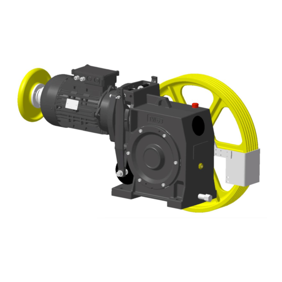
The drive is part of the protection device according to DIN EN81-1:2010-06 / 9.11 and EN81-20/5.6.7. 3.2 Description 3.2.1 Version with vertical motor position IMV1 TW63B Machine with motor version V3F (shown is the vertical IMV1 motor position - and brake monitoring - SA3/3.1) thyssenkrupp Aufzugswerke Version 09/2018... - Page 13 Operating manual Product Description TW63B drive Description of items for Fig. 3.2-1 Item Designation Item Designation Traction sheave (standard Driving gear (vertical version) version) Motor of type IMB5/V1 in accordance with building code BV6530-06/Bl.6 with integrated Operational brake special flange (standardised motors) or BV6530-06/Bl.1 with...
- Page 14 Operating manual Product Description TW63B drive 3.2.2 Version with horizontal IMB5 motor position TW63B machine with motor version V3F (shown with horizontal IMB5 motor position) Item Designation Item Designation Oil filling hole and ventilation Driving gear (horizontal version) (R3/4") Oil level monitoring (gauge glass) Oil drain (R3/4")
- Page 15 Operating manual Product Description TW63B drive 3.2.3 Version with emergency brake, NBS TW63B machine with NBS emergency brake system (shown in the horizontal IMB5 motor position, and left-hand traction sheave position) Item Designation Item Designation Disc brake - emergency brake...
- Page 16 TW63B drive 3.2.4 Version for traction sheave position in the shaft (SA9) Item Designation Item Designation TW63B machine, shown with Traction sheave shaft (SA9 vertical motor position IMV1 version) External bearing (bearing housing Traction sheave (SA9 version) with self-aligning bearing on adapter sleeve;...
-
Page 17: Functional Description
Operating manual Product Description TW63B drive 3.3 Functional description The TW63B machine (B = generation) is only operated with IMB5 motors. Machine with worm gear, anti-friction bearings, lubrication with synthetic gear oil for traction elevators 3.3.1 Gear The gear (gear drive) consists of a single-stage worm gear mounted on roller bearings. - Page 18 Operating manual Product Description TW63B drive The brake is released by electrically operated magnetic clamps with armature base plate. Release by manual operation 1. Apply the supplied brake release lever to the cast-on recesses of the ends of the brake blocks.
- Page 19 Operating manual Product Description TW63B drive name technical data unit machine design standard / SA9 diameter - DT rim width - B 9 x 8 6 x 8 7 x 8 8 x 9 6 x 9 7 x 9...
-
Page 20: Technology
Operating manual Technology TW63B drive 4 Technology 4.1 Technical data name technical data unit manufacturer ThyssenKrupp Elevator gear type TW63B axle distance gear ratio 54:1 / 48:1 / 33:1 / 48:2 / 43:3 vertical motor position: approx. 11 oil filling horizontal motor position: approx. -
Page 21: Dimensions Of Machine
Operating manual Technology TW63B drive 4.2 Dimensions of machine 4.2.1 Version with vertical motor position IMV1 TW63_30906_GER Item Designation Item Designation Mount of machine on machine Machine centre of gravity base frame Operation lever for manual brake release (plug-in) Fig. 4.2-1... - Page 22 Operating manual Technology TW63B drive 4.2.2 Version with horizontal motor position IMB5 TW63_30907_GER Item Designation Item Designation Mount of machine on machine Machine centre of gravity base frame Operation lever for manual brake release (plug-in) Fig. 4.2-2 thyssenkrupp Aufzugswerke Version 09/2018...
- Page 23 Operating manual Technology TW63B drive 4.2.3 Version with emergency brake, NBS (additional masses) TW63_30908_GER Fig. 4.2-3 thyssenkrupp Aufzugswerke Version 09/2018...
- Page 24 Operating manual Technology TW63B drive 4.2.4 Version for traction sheave in the shaft - SA9 (additional masses) TW63_30909_GER Item Designation Item Designation 260 with vertical motor position Mount of machine and external 310 with horizontal motor bearing on machine base frame position Fig.
-
Page 25: Machine Base Frame
675 mm (e.g. installations of type NO41/51) Installations with 2:1 or 4:1 rope suspension Weight of machine base frame: approx. 80 kg TW63 machine base frame NO/2:1 (shown with TW63B machine in vertical motor position) Item Designation Item... - Page 26 6079_NBO2 - standard sheet 60 720 12 00 0). The rope pulley has maintenance-free rolling bearings. TW63 machine base frame NO/MSR (shown is the machine base frame with rope pulley position on left and TW63B machine in horizontal motor position with NBS emergency brake system) Item...
- Page 27 6079_NBO2 - standard sheet 60 720 12 00 0). The rope pulleys have maintenance- free rolling bearings. TW63 machine base frame BO/MSR (shown is the machine base frame with rope pulley position on left and TW63B machine in horizontal motor position and traction sheave position on left) thyssenkrupp Aufzugswerke...
- Page 28 D450 D540 TW63_31007_ENG Table 4.3-1 4.3.4 Mounting parts for machine on machine base frame A set of bolting elements (M20-8.8) is available for mounting the TW63B NO/2:1, NO/MSR and BO/MSR machine on the machine base frame. thyssenkrupp Aufzugswerke Version 09/2018...
-
Page 29: Machine Base Frame Dimension Sheets
Operating manual Technology TW63B drive 4.4 Machine base frame dimension sheets 4.4.1 Version without rope pulley NO/2:1 TW63 machine base frame NO/2:1 with TW63B machine Item Designation Item Designation Horizontal motor position/traction Vertical motor position sheave position - right Additional insulation element for... - Page 30 Operating manual Technology TW63B drive Project planning dimensions: Project planning dimensions x1 and x2 (see dimension sheet for machine base frame NO/2:1) Intermediate values for x1 and x2 in the modular dimension of 68 mm possible traction sheave version configuration with machine on frame...
- Page 31 Operating manual Technology TW63B drive 4.4.2 Version with rope pulley NO/MSR/rope pulley position on left TW63 machine base frame - NO/MSR / left rope pulley position with TW63B machine Item Designation Item Designation Horizontal motor position/traction Vertical motor position sheave position - right...
- Page 32 Operating manual Technology TW63B drive Project planning dimensions: Rope clearance dimensions elevator car to counterweight ASL and wrap angle [°] traction sheave design ASL [mm] DT [mm] Remarks TW63_31006_ENG 1) machine with upright motor 2) machine with horizontal motor Table 4.4-2...
- Page 33 Operating manual Technology TW63B drive 4.4.3 Version with rope pulley NO/MSR/rope pulley position on right TW63 machine base frame - NO/MSR / right rope pulley position with TW63B machine Item Designation Item Designation Horizontal motor position/ Vertical motor position traction sheave position - right...
- Page 34 Operating manual Technology TW63B drive Project planning dimensions: Rope clearance dimensions elevator car to counterweight ASL and wrap angle [°] traction sheave design ASL [mm] DT [mm] Remarks TW63_31006_ENG 1) machine with upright motor 2) machine with horizontal motor Table 4.4-3...
- Page 35 Operating manual Technology TW63B drive 4.4.4 Version with rope pulley BO/MSR/rope pulley position on left TW63 machine base frame - BO/MSR / left rope pulley position with TW63B machine Item Designation Item Designation Horizontal motor position/ Vertical motor position traction sheave position - right...
- Page 36 Operating manual Technology TW63B drive Project planning dimensions: Rope clearance dimensions elevator car to counterweight ASL and wrap angle Clearance dimensions for ASL possible in the modular dimensions 68 mm version rope pulley version[mm] traction sheave D360 D450 D540 ...
- Page 37 Operating manual Technology TW63B drive 4.4.5 Version with rope pulley BO/MSR/rope pulley position on right TW63 machine base frame - BO/MSR / right rope pulley position with TW63B machine Item Designation Item Designation Horizontal motor position/ Vertical motor position traction sheave position - right...
-
Page 38: Encoder
4.5 Encoder The installation and connection are described in Chapter9.2.4 external operating manual in the Appendix Encoders are distinguished by type depending on the control system deployed. The following encoders are available for the TW63B. Encoder type Pulses 1024... -
Page 39: Brake
Operating manual Technology TW63B drive 4.6 Brake 4.6.1 Service brake Redundant electromagnetic dual-circuit outside shoe brake on the motor / worm shaft integrated in the gear or motor flange. The electric ventilation of the brake circuit takes place via magnetic clamps. The magnetic clamp are available in standard and in explosion-proof versions. -
Page 40: Transportation And Storage
Operating manual Transportation and storage TW63B drive 5 Transportation and storage 5.1 Packaging Fig. 5.1-1 The gear box casing is bolted directly onto the special pallet. Further packaging depends on the order and is country-specific (air/sea/land freight). Pay attention to the picture symbols on the packaging or other visible areas. -
Page 41: Transport
Operating manual Transportation and storage TW63B drive Dimensions and weight 3. Consult the label on the packaging below the transport hanger for the weight data. 4. Refer to the delivery note for the dimensions. 5. Consult the technical data for the approximate details. ... - Page 42 Operating manual Transportation and storage TW63B drive NOTE Damage during transport! May lead to product function impairments or function loss. Transport type only for machines without machine base frame Use only high-strength eyebolts (grade 8). Protect the fan hood against damage.
-
Page 43: Checking The Delivery
In the case of damage 4. Document any damage you have determined immediately in a sketch or photo and provide a written description in a damage report. 5. Forward the damage report immediately to thyssenkrupp Aufzugswerke GmbH. thyssenkrupp Aufzugswerke Version 09/2018... -
Page 44: Packaging Materials
Operating manual Transportation and storage TW63B drive 5.4 Packaging materials Specific transport equipment and shipping braces remain with the customer. Dispose of packaging materials in an environmentally compatible manner. 5.5 Ambient conditions 5.5.1 Intermediate storage Bare parts have no long-term preservation. -
Page 45: Installation
Operating manual Installation TW63B drive 6 Installation 6.1 Setting up the machine base frame The base frame is set up depending on the customer on supports, beams, a concrete pedestal or directly cast in the machine room floor. For reducing noise and sound transmission, we offer insulation elements, which can be inserted between the frame supports and the ground. -
Page 46: Installing And Aligning The Machine
Operating manual Installation TW63B drive Right-hand design Left-hand design Mount and secure the deflecting pulley with axle on the pulley supports. Set up the frame on the insulation elements according to the general arrangement drawing. 6.2 Installing and aligning the machine... - Page 47 Operating manual Installation TW63B drive Balance out uneven surfaces by inserting the enclosed shims. (Balancing by means of the supplied shims) Bolt the machine onto the frame, whereby the machine housing must not be tensioned. Align the rope grooves of the traction sheave and deflecting pulley in parallel.
-
Page 48: Mounting The Rope Guard
Operating manual Installation TW63B drive 6.3 Mounting the rope guard 1. Use the enclosed screws to bolt the rope guard onto the rope guard carrier. 2. Pivot the rope guard carrier to set the guard in such a way that the gap between the rope and guard on the rope run-in and run-out side of the traction sheave is as small as possible. -
Page 49: Connecting Motors
Operating manual Installation TW63B drive 6.4 Connecting motors NOTE Danger with potential damage to property! Can result in functional impairment or loss of function of the product. On connecting the motor, the enclosed terminal connecting plan in the motor connection box is to be complied with. - Page 50 Operating manual Installation TW63B drive 6.4.2 Connecting the motor line Item Designation Item Designation Cable with shielding braid Lock nut Lamellar insert Cap nut Abb. 6.4-2 1. Strip the insulation from the connection line. 2. Route cable through the cable gland.
- Page 51 The brake (2 magnetic clamps) is to be connected via the motor connection box (see Fig. 6.4 1). 6.4.5 Terminal connecting plan V3F Item Designation Item Designation Motor Posistor Brake (intermediate terminal Encoder connection) Fig. 6.4-3 Survey diagram for CEG MT132S and MOTORLIFT CMRF160L1 motors for TW63B thyssenkrupp Aufzugswerke Version 09/2018...
- Page 52 6.4.6 Terminal connecting plan AC2 TW63_39002_GER Item Designation Item Designation Motor (high speed) Motor (slow speed) Intermediate terminal connection, Posistor brake Forced ventilation with temperature switch (70°C) Fig. 6.4-4 Survey diagram TW63B pole changing (AC2) in design thyssenkrupp Aufzugswerke Version 09/2018...
-
Page 53: Commissioning
TW63B drive 7 Commissioning 7.1 Work steps For assembly, use only original construction and mounting parts from thyssenkrupp Aufzugswerke GmbH, as otherwise no warranty can be provided. Before commissioning the machine, the following points must be checked and carried out: ... -
Page 54: Emergency Operation
10.2. 7.2 Emergency operation The TW63B is equipped for emergency operation with a handwinding wheel and a brake release lever that is delivered separately. Emergency rescue of trapped persons 1. The brake release lever is to be applied to the cast-on recesses of the ends of the brake shoes. - Page 55 Operating manual Commissioning TW63B drive Item Designation Item Designation Brake shoes Brake release lever Fig. 7.2-1 thyssenkrupp Aufzugswerke Version 09/2018...
-
Page 56: Servicing / Maintenance
Operating manual Servicing / Maintenance TW63B drive 8 Servicing / Maintenance 8.1 Maintenance period Maintenance of the machine should take place within the framework of central maintenance of the elevator, at least once a year. 8.2 Maintenance measures Work step ... -
Page 57: Lubrication
Dispose of old oil as well as cloths contaminated with oil and grease according to prevailing regional regulations. Only use lubricants approved by THYSSENKRUPP AUFZUGSWERKE GmbH Oil change 1. Before the oil change, run the gear until it reaches operating temperature (at least 35°C). - Page 58 Operating manual Servicing / Maintenance TW63B drive WARNING Risk of scalding! Caution: hot oil represents a risk of scalding! Be particularly careful. 3. Close the oil drain after discharging the gear with sealing tape and the cap. 4. Fill the machine with the prescribed oil quantity through the upper opening on the gear housing (red cap, see Fig.
-
Page 59: Checking The Backlash
3. Fit a measuring attachment to the traction sheave; e.g. screw clamp. 4. Specify the measured radius (M). 5. Mark the measuring point. The radius (r) for the TW63B = 130 mm. 6. Attach a dial gauge with magnet stator at the gear drive housing and align to the measuring point (M). - Page 60 Operating manual Servicing / Maintenance TW63B drive 11. Use the formula below to calculate the backlash. 12. This measurement is to be carried out in at least three different positions on the worm gear toothing! Traction Worm wheel Fig. 8.4-1...
-
Page 61: Replacing The Brake Shoes
Operating manual Servicing / Maintenance TW63B drive 8.5 Replacing the brake shoes With a remaining lining thickness of less than or equal to 3 mm or if the linings are damaged (e.g. glazing), the brake linings must be replaced. 8.5.1 Disassembly 1. - Page 62 Operating manual Servicing / Maintenance TW63B drive 8.5.2 Installation 1. Mount the armature base plate on a new brake shoe. In doing so, lightly grease the rubbing surface between the armature base plate and armature screw. 2. Check the ease of movement of the armature base plate; adjust if necessary. It should be possible to move the armature base plate with low resistance on the screw.
-
Page 63: Setting And Checking The Brake Shoe Stroke And Armature Base Plate
Operating manual Servicing / Maintenance TW63B drive Stroke 0.3 + 0.1 Item Designation Item Designation Tightening screw Worm shaft Brake disc Magnetic clamp Cover ring Armature base plate Armature base plate screw Brake shoes Dial gauge Fig. 8.5-1 8.6 Setting and checking the brake shoe stroke and armature... - Page 64 Operating manual Servicing / Maintenance TW63B drive 4. Switch the drive to operate the brake shoes while checking the stroke of the brake shoes. The path should be 0.3 mm + 0.1 mm. Adjust the stroke 5. In the event of deviations, loosen the lock nuts ( , Item 7) Fig.
-
Page 65: Braking Deceleration Setting
Operating manual Servicing / Maintenance TW63B drive If brake test switches SA3 are present, these must be checked or adjusted after the brake adjustment. See 9 chapter 8.7 Braking deceleration setting The brake adjustment is to be carried out only with one effective brake shoe with the... -
Page 66: Replacing The Traction Sheave
Operating manual Servicing / Maintenance TW63B drive 8.9 Replacing the traction sheave 8.9.1 Disassembly 1. Switch off the installation power supply. 2. Secure the car and counterweight before starting work. 3. Take the load off the traction sheave and disengage the ropes. - Page 67 Operating manual Servicing / Maintenance TW63B drive 1. Place the new traction sheave on the conical shaft end of the worm wheel shaft. 2. Align the locations of the feather key and groove in relation to one another. 3. Push the traction sheave onto the worm wheel shaft.
-
Page 68: Replacing The Motor
Operating manual Servicing / Maintenance TW63B drive 8.10 Replacing the motor Order a motor with clutch hub. Note: the motors of the CEG and Motorlift makes already contain the clutch hub. 8.10.1 Disassembly 1. Switch off the installation power supply. -
Page 69: Replacing The Encoder
Operating manual Servicing / Maintenance TW63B drive 8.11 Replacing the encoder 8.11.1 Removal Before starting work, switch off the power to the installation and secure against reactivation. Unplug the encoder connection cable at the frequency inverter. Remove the central screw in the middle of the handwinding wheel hub. - Page 70 Operating manual Servicing / Maintenance TW63B drive Pos. Designation Pos. Designation Fan hood of motor Encoder Central screw for handwinding Handwinding wheel with hub wheel mount Encoder mount (spring plate) Screw for encoder mount Studs for mounting encoder on Clip nut...
-
Page 71: Check For Escaping Grease / Oil
Operating manual Servicing / Maintenance TW63B drive 8.12 Check for escaping grease / oil Examine the area around the bearing cover, brake drum and brake linings for traces of oil. Degree of soiling Procedure No escaping oil / grease... - Page 72 Operating manual Servicing / Maintenance TW63B drive Horizontal guide Vertical guide Item Designation Brake drum Roller bearing sealing disc Hub unit with integrated bearing cover Grease filling Gear oil Fig. 8.12-1 thyssenkrupp Aufzugswerke Version 09/2018...
-
Page 73: Special Versions (Optional)
Operating manual Special versions (optional) TW63B drive 9 Special versions (optional) 9.1 Overview of SA special versions Overview: SA 3* with brake monitoring (light barrier sensor) SA 3.1*with brake monitoring (microswitch) SA 9 Traction sheave position in the shaft (extended drive shaft with pedestal bearing... -
Page 74: Brake Monitoring Circuit
Operating manual Special versions (optional) TW63B drive 9.2 Brake monitoring circuit The brake monitoring circuit checks the brake shoes. It prevents motor movements when the brake is partially or fully closed and enables detection of any brake lining wear at an early stage. - Page 75 Operating manual Special versions (optional) TW63B drive way that when one contact of both switches closes the drive is prevented from starting With a correctly set brake test switch, all switch contacts must be interrupted with a closed brake. Before starting to set the sensor; the stroke of the brake shoes must be adjusted! Description, see ...
- Page 76 Operating manual Special versions (optional) TW63B drive Terminal connecting diagram - brake test switch SA3 - version Item Designation Item Designation Button 1 Button 2 A (black) - (blue) + (brown) Fig. 9.2-1 SA3.1 - version Item Designation Item Designation...
- Page 77 Operating manual Special versions (optional) TW63B drive Item Designation Item Designation Screw for compression spring Brake shoes on brake Adjusting screw Switch tappet Brake test switch Fig. 9.2-3 thyssenkrupp Aufzugswerke Version 09/2018...
- Page 78 Operating manual Special versions (optional) TW63B drive 9.2.4 Switch mounting SA15 The switch mounting for SA15 is described in the operating manual 'Explosion protection for machines (ATEX)'. thyssenkrupp Aufzugswerke Version 09/2018...
-
Page 79: Appendix
Operating manual Appendix TW63B drive 10 Appendix 10.1 Blocking clamp NOTE Leaving the blocking clamp fitted after completion of the installation work! Can damage the installation. Remove the blocking clamp after completion of the installation work. A blocking clamp that matches the traction sheave (rim width and design) is part of... -
Page 80: Tightening Torques
Tightness 10.9 12.9 Screw / bolt size Tightening torque (Nm) 1080 1300 1800 2150 Tab. 10.2-1 For assembly, use only original construction and mounting parts from thyssenkrupp Aufzugswerke GmbH, as otherwise no warranty can be provided. thyssenkrupp Aufzugswerke Version 09/2018... -
Page 81: Front Page Operating Manual Emergency Brake System Nbs
ABV, ESV and the shaft calculations can be found in the following operating manual Document number DE 65 999 01 86 0 EN 65 999 02 86 0 FR 9710 000 9229 Operating Manual Emergency Brake System NBS for: TW45C, TW63; TW130; TW160 ThyssenKrupp Aufzugswerke... - Page 82 TW63 W191 TW130 W263 W332 TW160 Operating Manual Explosion-proof Machines ATEX Supplement to Operating Manuals: TW63; W191; TW130; TW160; W263B; W332B ThyssenKrupp Aufzugswerke...
-
Page 83: Manufacturer Specifications Wachendorff, Encoder Wdg 100H
Encoder Overview: The following encoders are available for the TW45C 1. 1024 - (standard version) / 4096 - TTL (optional) for v < 1.5 m/s 1024 impulses for v < 1.5 m/s 4096 impulses Connection takes place with line SUB-D 9 ribbon connector and knurled screw UNC4-40 2. - Page 84 Part No. 9950 000 6021 mit 1024 Imp. Part No. 9950 000 6021 mit 4096 Imp.
- Page 85 Part No. 00 990 16 03 0 with 1024 pulses...
- Page 86 Part No. 00 990 19 03 0 mit 1024 Imp.
- Page 88 Wachendorff Automation GmbH & Co. KG Industriestrasse 7 D-65366 Geisenheim Tel.: +49 (0) 67 22 / 99 65 - 25 Fax: +49 (0) 67 22 / 99 65 - 70 www.wachendorff.de Hollow shaft Encoder WDG 100H Specifications Mechanical Data Housing - Servo flange: Aluminium - Housing:...
-
Page 89: Manufacturer Specifications Mayr, Roba-Stop-Z
Installation and Operational Instructions for ® ROBA-stop -Z Type 892.101.0 Size 125 (E073 01 046 000 4 EN) Design according to Drawing number: E073 01 046 000 1 10 Article number: 8227821 Please read these Operational Instructions carefully and follow them accordingly! Ignoring these Instructions may lead to malfunctions or to brake failure, resulting in damage to other parts. - Page 90 Installation and Operational Instructions for ® ROBA-stop -Z Type 892.101.0 Size 125 (E073 01 046 000 4 EN) Safety Regulations These Safety Regulations are user hints only and may not be complete! General Guidelines Guidelines for Electromagnetic Compatibility (EMC) DANGER In accordance with the EMC directives 2004/108/EC, the Danger of death! individual components produce no emissions.
- Page 91 Installation and Operational Instructions for ® ROBA-stop -Z Type 892.101.0 Size 125 (E073 01 046 000 4 EN) Safety Regulations These Safety Regulations are user hints only and may not be complete! Ambient temperature: 0 °C up to +45 °C Brake Storage ...
- Page 92 Installation and Operational Instructions for ® ROBA-stop -Z Type 892.101.0 Size 125 (E073 01 046 000 4 EN) Safety Regulations These Safety Regulations are user hints only and may not be complete! Standards, Directives and Regulations Used Liability The information, guidelines and technical data in these documents were up to date at the time of printing.
- Page 93 Installation and Operational Instructions for ® ROBA-stop -Z Type 892.101.0 Size 125 (E073 01 046 000 4 EN) 18.3 18.5 18.4 21/22 18.1 18.3 18.2 18.7 18.9/18.10 18.6 18.6 18.7 18.8/18.11 18.2 Fig. 1 Fig. 2 Fig. 3 11.4 11.3 Installation dimension 115 +1 mm 11.2...
- Page 94 Installation and Operational Instructions for ® ROBA-stop -Z Type 892.101.0 Size 125 (E073 01 046 000 4 EN) Parts List (Only use mayr original parts) Item Name Pcs. O-ring D60 x 3 Set screw M6 x 10 Brake body Magnetic coil Cap screw M8 x 85...
- Page 95 Installation and Operational Instructions for ® ROBA-stop -Z Type 892.101.0 Size 125 (E073 01 046 000 4 EN) Table 1: Technical Data Nominal braking torque (+60 %) 100 (2 x 50) Nm Nominal voltage 90 V Overexcitation voltage 180 V Overexcitation time span Coil power (nominal power at 20°C) 76 W...
- Page 96 Installation and Operational Instructions for ® ROBA-stop -Z Type 892.101.0 Size 125 (E073 01 046 000 4 EN) Application Installation Conditions ® ROBA-stop -Z brake for use as a holding brake with The eccentricity of the shaft end in relation to the mounting occasional EMERGENCY STOP braking actions (max.
- Page 97 Installation and Operational Instructions for ® ROBA-stop -Z Type 892.101.0 Size 125 (E073 01 046 000 4 EN) Installation Mount plastic hoses (17) onto both headless screws (16) in All the screws (except the cap screw Item 21) order to dampen vibration noises. and the set screws mounted by the customer must be tightened using the tightening torque Insert the elastomeric element (13) in the claws of the hub...
- Page 98 Installation and Operational Instructions for ® ROBA-stop -Z Type 892.101.0 Size 125 (E073 01 046 000 4 EN) Electrical Connection and Wiring Magnetic Field Removal AC-side Switching In safety applications, the rules for risk minimisation and error avoidance (e.g. redundance, diversity, resistance, monitoring The power circuit is etc.) must be observed during electrical activation.
- Page 99 Installation and Operational Instructions for ® ROBA-stop -Z Type 892.101.0 Size 125 (E073 01 046 000 4 EN) Permitted Shaft Misalignments Shaft Alignment ® ROBA -ES coupling compensates for radial, axial and angular Exact alignment of the coupling improves the running shaft misalignments (Fig.
- Page 100 Installation and Operational Instructions for ® ROBA-stop -Z Type 892.101.0 Size 125 (E073 01 046 000 4 EN) Braking Torque Dual Circuit Brake Functional Inspection ® –Z brake is equipped with a double safety The (nominal) braking torque is the torque effective in the shaft The ROBA-stop train on slipping brakes, with a sliding speed of 1 m/s referring to (redundant) braking system.
- Page 101 Installation and Operational Instructions for ® ROBA-stop -Z Type 892.101.0 Size 125 (E073 01 046 000 4 EN) Release Monitoring ® –Z brakes are supplied with manufacturer-side The ROBA-stop Customer-side Inspection of the Release Monitoring set release monitoring. after Mounting the Brake The customer-side contact is an NO contact.
- Page 102 Installation and Operational Instructions for ® ROBA-stop -Z Type 892.101.0 Size 125 (E073 01 046 000 4 EN) Maintenance Disposal ® ROBA-stop -Z brakes are mainly maintenance-free. The friction Our electromagnetic brake components must be disposed of lining pairing is robust and wear-resistant. This ensures a separately as they consist of different materials.
-
Page 103: Manufacturer Specifications Centaflex
Design for TW63... -
Page 105: Manufacturer Specifications Lapp Cable Gland Skintop Ms-Sc- M
U.I.LAPP GmbH GEBRAUCHSANWEISUNG SKINTOP® MS-M, MSR-M, MS-M-XL, MSR-M-XL Schulze-Delitzsch-Straße 25 MS-SC-M, MS-SC-M-XL D-70565 Stuttgart INSTRUCTION SHEET Tel.0711/7838-1010 Fax.0711/7838-2640 Internet:www.lappkabel.de Klemm- und Dichtbereich Clamping and Sealing range Approbationen Bezeichnung Approvals Product EN 50262 UL 514 B Größe/Size Kat.der Anzugsdreh- Klemm- Diameter ∅... - Page 106 Aufzugswerke GmbH Bernhäuser Strasse 45 73765 Neuhausen a. d. F. Germany E-mail: Doku.elevator.plant.de@thyssenkrupp.com Internet: www.thyssenkrupp-elevator-eli.com...
Need help?
Do you have a question about the TW63B and is the answer not in the manual?
Questions and answers