
Related Manuals for ThyssenKrupp Mini gearless DAF270


Summary of Contents for ThyssenKrupp Mini gearless DAF270
- Page 1 Operating Manual ® Mini gearless DAF270 A company of ThyssenKrupp Aufzugswerke ThyssenKrupp Elevator...
- Page 3 The responsibility for the content lies with the editor: THYSSENKRUPP AUFZUGSWERKE GmbH Preface We are pleased that you decided to purchase a quality product from THYSSENKRUPP AUFZUGSWERKE GmbH. This operating manual assists you in getting familiar with the drive for moving cars - the ®...
-
Page 5: Table Of Contents
8.2 Manufacturer's instructions for pulse encoder 8.3 Manufacturer's instructions for magnetic brake 8.4 Type test examination certificate for brake 8.5 Declaration of conformity for brake 8.6 Type examination certificate for calculation of traction sheave shaft ThyssenKrupp Aufzugswerke GmbH Issue 06.2004... -
Page 6: Safety
Disregard can lead to damages, hazards or failures. Inspection This symbol draws attention to the proper inspection sequence. These inspection notices must be observed in any case. Disregard can lead to injury to persons or damage to property. ThyssenKrupp Aufzugswerke GmbH Issue 06.2004... -
Page 7: General Safety Information
Organizational measures The owner or the installer must provide the necessary personal protective gear. All existing safety devices must be checked regularly in accordance with the maintenance plan. ThyssenKrupp Aufzugswerke GmbH Issue 06.2004... - Page 8 DAF270 shall exclusively be used as drive for lifts. Any other use or any use exceeding the scope of above definitions is regarded as use outside of the intended purpose. THYSSENKRUPP AUFZUGSWERKE cannot be hold liable for any damages resulting from this and for any damages which are caused by any errors of procedure.
- Page 9 AFETY Constructional modifications at DAF270 DAF270 is adjusted at the factory and delivered ready for work. In the case of any modifications of the machine THYSSENKRUPP AUFZUGSWERKE GmbH cannot be hold liable. Use of DAF270 and possible hazards DAF270 shall only be operated in a closed machine room, provided with cover and rope guard at the traction sheave or installed in a machine frame in the headroom.
-
Page 10: Transportation And Storage
• Remove transport aids after transport. Note the pictographs fastened on the packing or other visible places. Handle with care Keep dry Do not expose to Do not use handheld Fasten here heat grippers ThyssenKrupp Aufzugswerke GmbH Issue 06.2004... - Page 11 After receipt of goods make sure that there is no damage caused during transport. Information • Immediately document the damage noticed (drawing, photograph, description of damage). • Immediately send the respective documents to THYSSENKRUPP AUFZUGSWERKE GmbH. Unpacking Information • Dispose packing equipment in accordance with the environmental standards or make it available for further use.
-
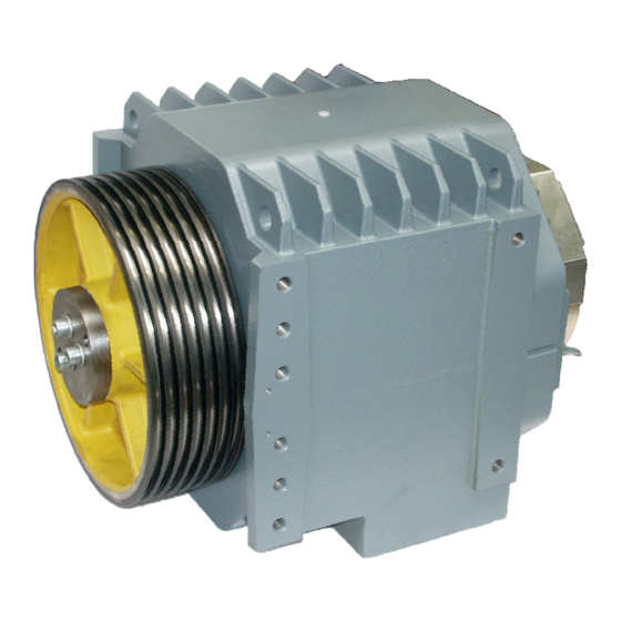
Page 12: Product Description
Cover plate for brake M12x 50 Traction sheave Encoder Ventilation opening Brake terminal box Casted housing Encoder connection Thread for fastening M16 Electromagnetic brake Motor terminal box Cable duct thermal contact Bearing bracket Cable duct motor connection ThyssenKrupp Aufzugswerke GmbH Issue 06.2004... - Page 13 3. Various traction sheave diameters 4. Various groove profiles and rope number at traction sheave available 5. (Optional) machine frame variants dependent on dimensions 6. Various types of brake ThyssenKrupp Aufzugswerke GmbH Issue 06.2004...
-
Page 14: Functional Description
The spring-applied armature disk of the respective magnetic brake is pressed against the brake lining of the rotor. The rotor is pushed and the second rotor lining acts on the rigid bearing surface of the brake or the bearing bracket. ThyssenKrupp Aufzugswerke GmbH Issue 06.2004... - Page 15 In case of a longer standstill, the friction linings can rust at the friction surfaces. Corresponding counter measures are to be made by the owner of the component. ThyssenKrupp Aufzugswerke GmbH Issue 06.2004...
- Page 16 Material number of the project planning form: German 9720 000 6756 English 9720 000 6778 Note: an installation frame, which makes delivery of the frame into the headroom easier, is optionally available. Please contact LiftEquip, if interested. ThyssenKrupp Aufzugswerke GmbH Issue 06.2004...
-
Page 17: Technical Data Machine
Weight machine (incl. traction [kg] sheave) Weight traction sheave [kg] Weight machine frame TK [kg] 400 - 650 Weight machine frame LE [kg] 400 - 600 1) Hardened groove flanks are used (min. 50 HRc). ThyssenKrupp Aufzugswerke GmbH Issue 06.2004... -
Page 20: Technical Data - Brake
84 kg Type test certificate number ABV 591 ABV 591 Release monitoring 1 x microswitch (per brake circuit) 24 VDC Switching voltage 10 ÷ 100 mA Switching capacity 0.15 mm Operating distance at setting screw ThyssenKrupp Aufzugswerke GmbH Issue 06.2004... -
Page 21: Pulse Encoder
HEIDENHAIN. Note: the build-on pulse encoder is standard and specially adapted to use with ThyssenKrupp inverter. Use of another type of inverter necessitates a pulse encoder adapted to the respective connected load. Use of a second encoder is not provided with DAF270 machine. -
Page 22: Dimensions
3. P PERATING ANUAL RODUCT ESCRIPTION Dimensions Dimensions DAF270 M 0xx M20 x 28 deep Brake connection Center of gravity Fig. 3 ThyssenKrupp Aufzugswerke GmbH Issue 06.2004... - Page 23 3. P PERATING ANUAL RODUCT ESCRIPTION Dimensions DAF270 L 0xx M20 x 28 deep Brake connection Center of gravity Fig. 4 ThyssenKrupp Aufzugswerke GmbH Issue 06.2004...
- Page 24 3. P PERATING ANUAL RODUCT ESCRIPTION Dimensions DAF270 M 008 (Tepper variant 1 : 1) M20 x 28 deep Brake connection Fig. 5 Center of gravity ThyssenKrupp Aufzugswerke GmbH Issue 06.2004...
-
Page 25: Machine Frame
The machine frame for DAF270 is designed for machine-room-less elevators to be placed in the headroom. The frame from ThyssenKrupp Aufzugswerke is intended for 2:1 suspension. The drive, terminal rope anchorages and the overspeed governor are also accomodated in the frame. The drive is attached at two profiles and supported by elastic elements. - Page 26 The shaft dimensions and the parallel distance of the ropes at the point of rope departure (ASL) (tailor-made acc. to customer specifications in accordance with available versions) define the frame design and dimensions. DAF270 with frame from LiftEquip for headroom installation. Fig. 7 ThyssenKrupp Aufzugswerke GmbH Issue 06.2004...
-
Page 27: Lubrication
3. P PERATING ANUAL RODUCT ESCRIPTION Lubrication DAF270 DAF270 has lifetime-lubricated rolling bearings. The bearings do not require lubrication. ThyssenKrupp Aufzugswerke GmbH Issue 06.2004... -
Page 28: Name Plate
3. P PERATING ANUAL RODUCT ESCRIPTION Name plate DAF270 Version 1. THYSSENKRUPP AUFZUGSWERKE GmbH 120 kN Line Column Meaning Machine type Serial No. / year of construction Design Protection class Insulation class Mode of operation Weight of machine [ kg ] Rated output [ kW ] Motor speed [ U / Min.]... - Page 29 Voltage [ V ] (star connection) Strength of current [ A ] Efficiency Starting torque [ Nm ] Power consumption [ A ] Frequency [ Hz ] Note on further data Traction sheave ∅; max. number of ropes; rope ∅ ThyssenKrupp Aufzugswerke GmbH Issue 06.2004...
-
Page 30: Mounting Of Machine
When the ropes are tensioned, the machine shall be arranged horizontally aligned at the base plate. Use metal plates to ensure that the base is perfectly horizontal. ThyssenKrupp Aufzugswerke GmbH Issue 06.2004... - Page 31 (due to exchanged traction sheave, for example) verify that the machine is properly aligned and re-align, if required. Note: when the machine is completely installed, tighten the fastening screws with the pre-set torque. See chapter 8.1. ThyssenKrupp Aufzugswerke GmbH Issue 06.2004...
-
Page 32: Motor Connection
Grd. Fig. 8 Fig. 9 Temperature monitoring motor Connect terminal connection "Th" (thermistor) and PTC tripping device (or frequency inverter connection provided for that purpose. Voltage applied shall not exceed 2.5 V. ThyssenKrupp Aufzugswerke GmbH Issue 06.2004... -
Page 33: Connection Of Magnetic Brake
Brake and encoder connection Fig. 10 Brake housing Conn. PTC resistors motor Brake test switch D Encoder connection Brake voltage connection Fastening bow Brake test switch Bearing bracket Terminal box Cover plate brake Brake test switch C Encoder ThyssenKrupp Aufzugswerke GmbH Issue 06.2004... - Page 34 Note: it is recommended to adhere to the instructions and recommendations of the brake manufacturer as the performance of the brake in service mainly depends on the circuit selected. See chapter 8.3. ThyssenKrupp Aufzugswerke GmbH Issue 06.2004...
- Page 35 When replacing make sure that the switch setting is in accordance with the instructions in chapter 7.3. Check the switches for proper setting and correct function. Connection release monitoring switch Break contact connection black Input connection brown Make contact connection blue Fig. 12 ThyssenKrupp Aufzugswerke GmbH Issue 06.2004...
- Page 36 Further details see chapter 8.3 Manufacturer's instructions. After connecting check brake and monitoring switches for correct functioning. Note: an appropriate access to the brake and microswitches for the inspection, adjustment or replacement works must be possible. ThyssenKrupp Aufzugswerke GmbH Issue 06.2004...
- Page 37 Brake lining Brake coil body C Brake disc D Anchor disc D Brake coil body D Cheese head screw (switch fastening) Setting screw brake release C Brake release switch C (release monitoring) Eyebolt Terminal box ThyssenKrupp Aufzugswerke GmbH Issue 06.2004...
- Page 38 4. M PERATING ANUAL OUNTING ACHINE Connecting cables magnetic brake Fig. 14 ThyssenKrupp Aufzugswerke GmbH Issue 06.2004...
-
Page 39: Connection Of Encoder
Connection to control by means of a 10 m long connecting cable with 15-pole sub-D connector. Pin assignment of connector see chapter 8.2 „Manufacturer's instructions“. Description and technical data for encoder connection see chapter 3.5. ThyssenKrupp Aufzugswerke GmbH Issue 06.2004... -
Page 40: Schematic Diagram
4. M PERATING ANUAL OUNTING ACHINE Schematic diagram DAF270 ThyssenKrupp Aufzugswerke GmbH Issue 06.2004... -
Page 41: Putting Into Service
Never put the installation into service without brake test switches by disconnecting the check-back or brake test switches and resetting the non- volatile memory (EPROM). Disregard may cause danger to life of persons. ThyssenKrupp Aufzugswerke GmbH Issue 06.2004... - Page 42 Check motor bearings for wear (noise, backlash) • Check protective and safety equipment; test for correct working • Check protective and safety equipment; check danger and instruction signs; check signs for proper affixing and visibility ThyssenKrupp Aufzugswerke GmbH Issue 06.2004...
-
Page 43: Drive Brake Test
Motor braking may lead to wrong test results. • Determine deceleration for 1. brake circuit using a measuring device • Compare measurement and reference value • Remove continuous voltage supply at continuously open 2. brake circuit and connect to 1. brake circuit. ThyssenKrupp Aufzugswerke GmbH Issue 06.2004... - Page 44 • Repeat described testing for 2. brake circuit. Attention: when the brake is tested, the original switching condition is to be established (operation of both brake coils at the same time and connection of brake test switch). ThyssenKrupp Aufzugswerke GmbH Issue 06.2004...
- Page 45 0.35 mm max. 0.6 mm ± 0,1 1700 3400 Nm 0.35 mm max. 0.7 mm Rated air gap brake closed (at zero current), new lining Limit air gap brake closed (at zero current), worn off lining ThyssenKrupp Aufzugswerke GmbH Issue 06.2004...
- Page 46 Hexagon socket M12x200 Connection box brake 10 Protecting plate Dial gauge 11 Hexagon socket M8x150 Dial gauge holder 12 Brake magnet housing D Transport eyebolt M12 13 Encoder Encoder connection 14 Hexagon socket M12 x 20 ThyssenKrupp Aufzugswerke GmbH Issue 06.2004...
-
Page 47: Replacing Of Traction Sheave
Hexagon socket M 16 x 50– 8.8 microencapsulated Tightening torque = 195 Nm Motor shaft Motor housing Motor connection box Forcing hole Installation sequence traction sheave replacement Disassembly: • Switch off power supply; secure car and counterweight • Remove rope fixing beam ThyssenKrupp Aufzugswerke GmbH Issue 06.2004... - Page 48 When the traction sheave is to be replaced, enclosed new micro- encapsulated screws must be used. Observe screw strength and tightening torque! Note: only use micro-encapsulated screws twice, since otherwise the adhesive force is no longer effective ThyssenKrupp Aufzugswerke GmbH Issue 06.2004...
-
Page 49: Replacing Of Pulse Encoder
Unscrew clamp bolt at female encoder component using hexagon socket wrench M2.5 (2 screws pos. 3) • Unscrew encoder and fixing strap at brake (2 x M8) • Carefully remove encoder from shaft end into axial direction ThyssenKrupp Aufzugswerke GmbH Issue 06.2004... - Page 50 Fixing strap Brake housing Encoder Shaft end Connecting line Fig. 18 Clamping bolt Note: re-adjust the encoder with the pulse encoder being replaced or the rotor position changed. Proceeding see operating manual of frequency inverter. ThyssenKrupp Aufzugswerke GmbH Issue 06.2004...
-
Page 51: Replacing Of Brake Monitoring Switch
(switching frequency, torque adjustment, natural drive vibration). The brake must be completely exchanged, if the noise behaviour of the brake rises to an inadmissible level. An exchange of the damping elements is only possible at the manufacturer. ThyssenKrupp Aufzugswerke GmbH Issue 06.2004... -
Page 52: Replacing Of Brakes
Fig. 19 Motor shaft Brake magnet housing Hexagon screw M8 x 40 Hexagon screw M12 x 200 Motor housing Encoder Bearing bracket 10 Fixing strap Braking rotor 11 Toothed sleeve Armature base plate O ring ThyssenKrupp Aufzugswerke GmbH Issue 06.2004... - Page 53 In case of disregard, the brake rotor blocks and the brake housing cannot be moved and aligned while fitting the screws. • Mount brake and second brake rotor; tighten fastening screws and observe proper tightening torque. ThyssenKrupp Aufzugswerke GmbH Issue 06.2004...
- Page 54 • Remove transport contrivances at car and counterweight • When the drive or the brakes are replaced, check the drive brake for correct functioning before you start operation. See description in chapter 6.2. ThyssenKrupp Aufzugswerke GmbH Issue 06.2004...
-
Page 55: Annex
To observe the required torque, tighten the screws using a torque spanner! Dimension Tightening torque M [Nm] Strength 10.9 12.9 1150 Attaching encoder on shaft Clamping bolt 2,5 Nm Attaching encoder on brake M4 x 4 1,0 Nm ThyssenKrupp Aufzugswerke GmbH Issue 06.2004... -
Page 56: Manufacturer's Instructions For Pulse Encoder
PERATING ANUAL NNEX Manufacturer's instruction for pulse encoder ThyssenKrupp Aufzugswerke GmbH Issue 06.2004... - Page 57 PERATING ANUAL NNEX Mounting dimensions 4 x M4 Installation ThyssenKrupp Aufzugswerke GmbH Issue 06.2004...
- Page 58 PERATING ANUAL NNEX ThyssenKrupp Aufzugswerke GmbH Issue 06.2004...
- Page 59 PERATING ANUAL NNEX ∅ 87 SW3 (2X)) Md = 2,5 ± 0,5Nm 10 000 mm ThyssenKrupp Aufzugswerke GmbH Issue 06.2004...
- Page 60 Pin assignment 15-pole sub-D connector (pin) Data Clock Contact Green Yellow Blue nicht Color Gray Purple Yellow Not Assigned belegt Black Black Black Black Inside Screen Contact Brown White White White Blue Color Green Green Black ThyssenKrupp Aufzugswerke GmbH Issue 06.2004...
-
Page 61: Manufacturer's Instructions For Magnetic Brake
8. A PERATING ANUAL NNEX Manufacturer’s instructions - Brake ThyssenKrupp Aufzugswerke GmbH Issue 06.2004... - Page 62 8. A PERATING ANUAL NNEX ThyssenKrupp Aufzugswerke GmbH Issue 06.2004...
- Page 63 8. A PERATING ANUAL NNEX ThyssenKrupp Aufzugswerke GmbH Issue 06.2004...
- Page 64 8. A PERATING ANUAL NNEX ThyssenKrupp Aufzugswerke GmbH Issue 06.2004...
- Page 65 8. A PERATING ANUAL NNEX ThyssenKrupp Aufzugswerke GmbH Issue 06.2004...
-
Page 66: Type Test Examination Certificate For Brake
PERATING ANUAL NNEX 8.4. Type test examination certificate for brake ThyssenKrupp Aufzugswerke GmbH Issue 06.2004... - Page 67 PERATING ANUAL NNEX ThyssenKrupp Aufzugswerke GmbH Issue 06.2004...
- Page 68 PERATING ANUAL NNEX ThyssenKrupp Aufzugswerke GmbH Issue 06.2004...
- Page 69 PERATING ANUAL NNEX ThyssenKrupp Aufzugswerke GmbH Issue 06.2004...
-
Page 70: Declaration Of Conformity For Brake
PERATING ANUAL NNEX 8.5. Declaration of conformity for brake ThyssenKrupp Aufzugswerke GmbH Issue 06.2004... - Page 71 PERATING ANUAL NNEX ThyssenKrupp Aufzugswerke GmbH Issue 06.2004...
-
Page 72: Type Examination Certificate For Calculation Of Traction Sheave Shaft
PERATING ANUAL NNEX Type examination certificate for calculation of traction sheave shaft ThyssenKrupp Aufzugswerke GmbH Issue 06.2004... - Page 76 ThyssenKrupp Aufzugswerke GmbH A company of ThyssenKrupp Elevator Bernhäuser Strasse 45 73765 Neuhausen a. d. F. Germany Tel.: +49 7158/12-0 Fax: +49 7158/12-2585 E-Mail: info@tke-aufzuege-de.thyssenkrupp.com www.thyssenkrupp-aufzuege.com...