Table of Contents
Advertisement
Quick Links
Quick Start
Overview
f
WARNING!
Read all warning, cautions, notes and installation instructions before installing or servicing this equipments.
This quick start describes how to install, configure, and troubleshoot the NetVanta 1561i-04 industrial L2+ managed GbE switch. This next generation industrial-
grade Ethernet switch has two 10M/100M/1G RJ-45 and two 1G SFP ports that provide powerful L2 and basic L3 features as well as Carrier Ethernet OAM, CFM,
ERPS, and EPS functionality.
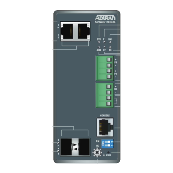
Figure 1
■
"Installing the NetVanta 1561i-04 Switch"
■
"Supplying Power to the NetVanta 1561i-04 Switch"
■
"Connecting the DI/DO Relay Wires to the Switch"
■
"Installing SFP Modules"
on page 5
■
"Connecting to the Switch"
on page 5
■
"Understanding the Status LEDs"
■
"Resetting the Switch"
on page 8
■
"Troubleshooting the Switch"
■
"Product Specifications"
on page 8
f
WARNING!
WARNING indicates a hazard which, if not
avoided, could result in death, injury or
serious property damage.
ADTRAN
NetVanta 1561i-04
Industrial L2+ Managed GbE Switch
below shows the front panel layout of the switch.
on page 2
on page 4
on page 4
on page 7
on page 8
10/100/1000
RJ-45 Ports
Port Status
LEDs
100/1000
SFP Ports
Port Status
LEDs
Figure 1. NetVanta 1561i-04 Front Panel Layout
f
CAUTION!
CAUTION indicates a hazard which, if not
avoided, could result in service interruption,
damage to the equipment, or minor property
damage.
System LED
Power 1 LED
Ring Master LED
Rapid Chain LED
Power 2 LED
Alarm LED
12/24/48 VDC
Dual Input
Digital Input
Voltage
Digital Output
Relay
CONSOLE
Port
DIP Switch
(Ring Settings)
Reset
Button
Ground Screw
g
NOTES inform the user of additional, but
important, information or features.
February 2021
617111561F1-13A
P/N: 17111561F1
NOTE
Advertisement
Table of Contents

Related Manuals for ADTRAN NetVanta 1561i-04


Summary of Contents for ADTRAN NetVanta 1561i-04
- Page 1 Read all warning, cautions, notes and installation instructions before installing or servicing this equipments. This quick start describes how to install, configure, and troubleshoot the NetVanta 1561i-04 industrial L2+ managed GbE switch. This next generation industrial- grade Ethernet switch has two 10M/100M/1G RJ-45 and two 1G SFP ports that provide powerful L2 and basic L3 features as well as Carrier Ethernet OAM, CFM, ERPS, and EPS functionality.
- Page 2 Prior to Installation Before installing the equipment, inspect the switch. If damage has occurred during shipping, file a claim with the carrier, and then contact ADTRAN Customer Support. For more information, refer to the product warranty available online at https://adtran/wp_support_warranty.
- Page 3 Wall Mounting the NetVanta 1561i-04 Switch Follow these instructions to mount the NetVanta 1561i-04 switch to a wall using the enclosed wall mounting kit: 1. Attach the wall-mounting brackets to the rear panel of the switch chassis and drive the provided screws into the metal screw receptacles on the back of the...
- Page 4 NOTE The NetVanta 1561i-04 switch has dual power inputs. If only one power input is required, install the DC terminal block into one of the specific power inputs (labeled P1 or P2). If dual power is being used, repeat the steps outlined below to install the second input.
-
Page 5: Installing Sfp Modules
This product is intended for use with a Class 1 Laser module that complies with FDA 21 CFR 1040.10, 1040.11 and IEC 60825-1. For continued compliance with the above standards, only approved Class 1 Laser modules from an ADTRAN approved vendor list (located on the ADTRAN website) should be installed in this product. - Page 6 Initial Switch Configuration Using a Web Browser After powering up the switch for the first time, you can perform the initial switch configuration using a web browser. To begin with the initial configuration stage, reconfigure your PC’s IP address and subnet mask to make sure the PC can communicate with the switch. After changing PC’s IP address (for example, 10.10.10.250), then access the web interface of the switch using the switch’s default IP address as shown below.
-
Page 7: Understanding The Status Leds
4. Login with the default user name (admin) and password (password). Understanding the Status LEDs The LEDs on the NetVanta 1561i-04 switch’s front panel provide you with the ability to monitor the device status. The following section describes the types of LEDs available on the switch device. -
Page 8: Resetting The Switch
7 to 12 seconds Blinking Green All LED lights stay ON Troubleshooting the Switch The following table provides basic troubleshooting steps for the NetVanta 1561i-04 switch when LED behavior indicates a problem. LED Behavior Possible Cause Basic Troubleshooting Steps 1. Verify that the correct power cord is connected firmly to the switch and to the DC outlet socket. - Page 9 2. This device must accept any interference received, including interference that may cause undesired operation. ■ Changes or modifications not expressly approved by ADTRAN could void the user's authority to operate this equipment. ■ This equipment has been tested and found to comply with the limits for a Class A digital device, pursuant to part 15 of the FCC Rules. These limits are designed to provide reasonable protection against harmful interference when the equipment is operated in a commercial environment.
Need help?
Do you have a question about the NetVanta 1561i-04 and is the answer not in the manual?
Questions and answers