Table of Contents
Advertisement
Quick Links
Quick Start
Overview
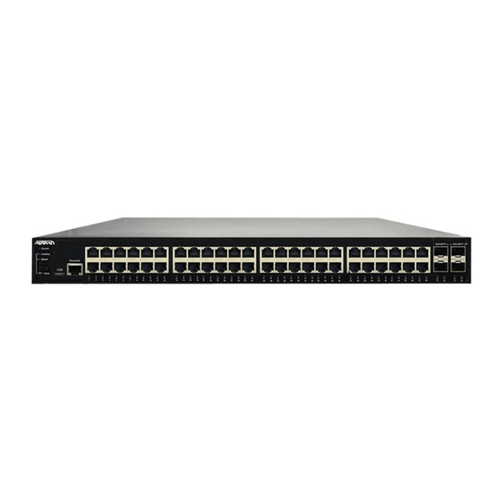
This quick start describes how to install, configure, and troubleshoot the NetVanta 1560-48-370W, 48-port Managed GbE 370W PoE+ Switch. Figures 1 and 2 show
the Front and Rear Panel layouts of the switch.
■
on page 1
■
■
■
■
on page 7
■
SYS
CONSOLE
LED
NetVanta 1560-48-370W
LINK/ACT/SPD
SYSTEM
LNK/ACT/SPD
Mode LED
PoE
MODE/RESET
PoE
MODE
Mode LED
Button
Installing the Switch
g
NOTE
Refer to the national, state and local electrical codes for the requirements for power, grounding, wiring, and installation methods.
f
WARNING!
Read all warnings, cautions, notes and installation instructions before installing or servicing this equipment.
Package Contents
■ NetVanta 1560-48-370W switch
■ AC power cord
■ DB-9 to RJ-45 cable
■ Micro-USB to USB cable
■ Four adhesive rubber feet
■ Mounting kit (two brackets and eight screws)
■ Quick Start
f
CAUTION!
The NetVanta 1560-48-370W is intended for indoor use only. Ethernet, PoE cables, and attached equipment are intended for use within the same building with
equipotential bonding, and not intended to be placed in separate buildings or structures. Failure to deploy as described could result in permanent damage from
lightning or other electrical events and voids the warranty.
NetVanta 1560-48-370W
48-port Managed GbE 370W PoE+ Switch
on page 5
on page 6
on page 6
on page 7
Port
USB
CONSOLE
1
2
3
4
5
6
7
8
9
10
11
12
Figure 1. Front Panel Layout
10/100/1000
RJ-45 with PoE+
13
14
15
16
17
18
19
20
21
22
23
24
25
26
27
Port Status
LEDs
Figure 2. Rear Panel Layout
28
29
30
31
32
33
34
35
36
37
38
39
40
41
42
43
AC Line: 100-240V 50-60Hz
May 2020
617101568PF2-13A
P/N: 17101568PF2
1G/10G
SFP+ Ports
44
45
46
47
48
49
50
51
52
Power Connection
AC Line: 100-240V 50-60Hz
Advertisement
Table of Contents

Related Manuals for ADTRAN NetVanta 1560-48-370W


Summary of Contents for ADTRAN NetVanta 1560-48-370W
- Page 1 Quick Start P/N: 17101568PF2 Overview This quick start describes how to install, configure, and troubleshoot the NetVanta 1560-48-370W, 48-port Managed GbE 370W PoE+ Switch. Figures 1 and 2 show the Front and Rear Panel layouts of the switch. ■ “Installing the Switch”...
- Page 2 2. Connect AC Power 3. Install SFP+ Modules Installation Steps To install the NetVanta 1560-48-370W switch, complete the following steps: Mount the Switch The switch can be mounted in a 19-inch rack, or on a desk or shelf. Mounting in a 19-inch Rack To mount the switch into a 19-inch rack, complete the following steps.
- Page 3 NOTE Rack mount brackets are a default accessory with the unit; spare brackets can be ordered through ADTRAN, part number: 1700519F1. Figure 4. Attaching Brackets to the Rack Post Mounting on a Desk or Shelf To mount the switch on a desk or shelf, complete the following steps.
- Page 4 Class 1 Laser modules from an ADTRAN approved vendor list (located on the ADTRAN website) should be installed in this product. ADTRAN cannot certify system integrity with other laser modules. The CDRH Laser Class emitted by the Fiber Optic Laser Module Component is Class I or 1 when installed in the end-product with the fiber-optic cable removed.
- Page 5 Initially Configuring the Switch The Switch can be configured by two methods: ■ Web based Graphical User Interface (GUI) ■ Command Line Interface (CLI) Initial Switch Configuration Using a Web Browser After powering up the switch for the first time, you can perform the initial switch configuration using a web browser. To begin with the initial configuration stage, you need to reconfigure your PC’s IP address and subnet mask to make sure the PC can communicate with the switch.
- Page 6 NOTE There are many terminal emulation applications available on the web. PuTTY, SecureCRT, and HyperTerminal are a few examples. Complete the following steps: 1. Connect a Micro USB cable to the micro USB CONSOLE port or connect a DB-9 to RJ-45 serial cable to the RJ-45 CONSOLE port. 2.
- Page 7 Color State Description The port is enabled, has established a link to a connected device, and the connection speed is 10 Gbps. Flashing The port is transmitting/receiving packets, and the connection speed is 10 Gbps. The port is enabled, has established a link to connected device, and the connection speed is 1 Gbps. SFP+ Ports ...
- Page 8 2. This device must accept any interference received, including interference that may cause undesired operation. ■ Changes or modifications not expressly approved by ADTRAN could void the user's authority to operate this equipment. ■ Changes or modifications not expressly approved by ADTRAN will void the warranty.
Need help?
Do you have a question about the NetVanta 1560-48-370W and is the answer not in the manual?
Questions and answers