
Related Manuals for ADTRAN 1702594G1 NetVanta 1234


Summary of Contents for ADTRAN 1702594G1 NetVanta 1234
-
Page 1: Hardware Installation Guide
NetVanta 1230 Series Fast Ethernet Switch Hardware Installation Guide 1702594G1 NetVanta 1234 1702595G1 NetVanta 1234P 1702598G1 NetVanta 1238 1702599G1 NetVanta 1238P 61702594G1-34C April 2013... - Page 2 To the Holder of the Manual The contents of this manual are current as of the date of publication. ADTRAN reserves the right to change the contents without prior notice. In no event will ADTRAN be liable for any special, incidental, or consequential damages or for commercial losses even if ADTRAN has been advised thereof as a result of issue of this publication.
- Page 3 NetVanta 1230 Series Hardware Installation Guide Conventions Conventions Notes provide additional useful information. Cautions signify information that could prevent service interruption or damage to the equipment. Warnings provide information that could prevent injury or endangerment to human life. 61702594G1-34C Copyright © 2013 ADTRAN, Inc.
- Page 4 These units contain no user-serviceable parts. They should only be serviced by qualified service personnel. Additional safety guidelines, such as Waste Electrical and Electronic Equipment (WEEE), are given in the document NetVanta Safety and Regulatory Information available at https://supportforums.adtran.com. Save These Important Safety Instructions Copyright © 2013 ADTRAN, Inc. 61702594G1-34C...
- Page 5 Denial of Service (DoS) attacks, loss or theft of data, and the unauthorized or illegal use of said equipment. ADTRAN OFFERS NO WARRANTIES, EITHER EXPRESSED OR IMPLIED, REGARDING THE PREVENTION, DETECTION, OR DETERRENCE OF TOLL FRAUD, NETWORKING ATTACKS, OR UNAUTHORIZED, ILLEGAL, OR IMPROPER USE OF ADTRAN EQUIPMENT OR SOFTWARE.
- Page 6 Service and Warranty NetVanta 1230 Series Hardware Installation Guide Copyright © 2013 ADTRAN, Inc. 61702594G1-34C...
-
Page 7: Table Of Contents
Connector Pin Definitions..........29 61702594G1-34C Copyright © 2013 ADTRAN, Inc. - Page 8 Table of Contents NetVanta 1230 Series Hardware Installation Guide Copyright © 2013 ADTRAN, Inc. 61702594G1-34C...
- Page 9 Wallmount Installation ............26 61702594G1-34C Copyright © 2013 ADTRAN, Inc.
- Page 10 List of Figures NetVanta 1230 Series Hardware Installation Guide Copyright © 2013 ADTRAN, Inc. 61702594G1-34C...
-
Page 11: List Of Tables
Table A-3. 1000Base-T Gigabit Ethernet Port Pinouts ........30 61702594G1-34C Copyright © 2013 ADTRAN, Inc. - Page 12 List of Tables NetVanta 1230 Series Hardware Installation Guide Copyright © 2013 ADTRAN, Inc. 61702594G1-34C...
-
Page 13: Introduction
Supplying Power to the Unit on page 26 For information on configuring a specific application, refer to the configuration guides or the AOS Command Reference Guide provided on the ADTRAN Support Community at https:supportforums.adtran.com. 61702594G1-34C Copyright © 2013 ADTRAN, Inc. -
Page 14: Physical Descriptions
SFP slots G1 and G2 provide up to 1 Gbps and SPF slots G3 and G4 provide up to 2.5 Gbps fiber connectivity. For a list of supported SFP modules, visit the ADTRAN website at http://www.adtran.com. -
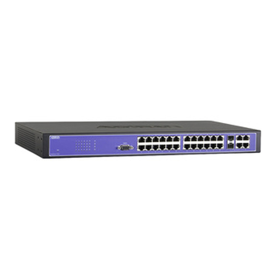
Page 15: Figure 1. Netvanta 1234 Front Panel Layout
Gigabit Ethernet (RJ-45) interfaces numbered G1 and G2 and share status LEDs. (Use either the RJ-45 connectors for up 100/1000 Mbps copper connectivity or the SFP slots for 1 Gbps fiber connectivity. The SFP slots have precedence.) Slots G3 and G4 provide fiber connectivity at 1 or 2.5 Gbps. 61702594G1-34C Copyright © 2013 ADTRAN, Inc. -
Page 16: Figure 2. Netvanta 1234 Rear Panel Layout
The PoE LED is located on the left side of the unit and indicates that the port LEDs are displaying PoE status. VCID LED (Future Release) The VCID LED is located on the left side of the unit and indicates that the port LEDs are displaying VCID. Copyright © 2013 ADTRAN, Inc. 61702594G1-34C... -
Page 17: Figure 4. Netvanta 1234P Rear Panel Layout
Connection directly to an external modem requires a cross-over cable. Power Connection The rear panel has a power input to the AC universal power supply. Please refer to Supplying Power to the Unit on page 26 for connection details. 61702594G1-34C Copyright © 2013 ADTRAN, Inc. -
Page 18: Figure 5. Netvanta 1238 Front Panel Layout
The SFP slots have precedence.) Slots G3 and G4 provide fiber connectivity at 1 or 2.5 Gbps. NetVanta 1238 Rear Panel Design The NetVanta 1238 rear panel is shown below. Refer to Appendix A on page 29 for pinouts. AC INPUT Figure 6. NetVanta 1238 Rear Panel Layout Copyright © 2013 ADTRAN, Inc. 61702594G1-34C... -
Page 19: Figure 7. Netvanta 1238P Front Panel Layout
VCID. LED Mode Switch (Future Release) The LED mode switch is located on the left side of the unit and is used to toggle Ports 1 through 48 between link/activity and VCID display modes. 61702594G1-34C Copyright © 2013 ADTRAN, Inc. -
Page 20: Figure 8. Netvanta 1238P Rear Panel Layout
Connection directly to an external modem requires a cross-over cable. Power Connection The rear panel has a power input to the AC universal power supply. Please refer to Supplying Power to the Unit on page 26 for connection details. Copyright © 2013 ADTRAN, Inc. 61702594G1-34C... -
Page 21: Table 1. Front Panel Led Descriptions
(1 - 24 NetVanta Green (solid) Powered device is connected. 1234P) (1 - 48 NetVanta Green (flashing) The port has detected a PoE fault. 1238P) Ports G1 through G4 are always in LINK/ACT mode. 61702594G1-34C Copyright © 2013 ADTRAN, Inc. -
Page 22: Product Specifications
AC Input Power: 110 to 240 VAC Storage Temperature: -20C to 70C Operating Temperature: 0C to 50C Relative Humidity: Up to 95 percent, noncondensing Copyright © 2013 ADTRAN, Inc. 61702594G1-34C... -
Page 23: Unit Installation
ADTRAN's for this purpose will void the user's warranty. • PoE cables are intended for intrabuilding use only. Connecting an ADTRAN PoE unit directly to PoE cables that run outside the building in which the unit is housed will void the user's warranty and could create a fire or shock hazard. -
Page 24: Mounting Options
Apply power to the unit (refer to Supplying Power to the Unit on page 26). To avoid damaging the unit, use only the screws included in the shipment when attaching mounting ears to the chassis. Copyright © 2013 ADTRAN, Inc. 61702594G1-34C... - Page 25 Have an assistant hold the unit in position as you install two #6 to #10 (1 inch or greater in length) wood screws through the unit’s brackets and into the mounted board (see Figure 9 on page 26). Proceed to the steps given in Supplying Power to the Unit on page 61702594G1-34C Copyright © 2013 ADTRAN, Inc.
-
Page 26: Supplying Power To The Unit
If you must use an extension cable, use a 3-wire cable with properly grounded plugs. After the NetVanta is powered on, the LED indicators will flash momentarily. This flashing represents a reset of the system. Copyright © 2013 ADTRAN, Inc. 61702594G1-34C... - Page 27 ADTRAN Support Community. For details on the CLI, refer to the AOS Command Reference Guide. All other related documents are also available online at https://supportforums.adtran.com. 61702594G1-34C Copyright © 2013 ADTRAN, Inc.
- Page 28 Unit Installation NetVanta 1230 Series Hardware Installation Guide Copyright © 2013 ADTRAN, Inc. 61702594G1-34C...
-
Page 29: Appendix A. Connector Pin Definitions
Unused Receive Negative 7, 8 — Unused Table A-2. SFP Slot Pinouts Name Name RX_LOS RGND RGND RX_DAT- RGND RX_DAT+ MOD_DEF(0) RGND MOD_DEF(1) VddR MOD_DEF(2) VddT TX_DISABLE TGND TGND TX_DAT+ TGND TX_DAT- TX_FAULT TGND 61702594G1-34B Copyright © 2012 ADTRAN, Inc. -
Page 30: Table A-3. 1000Base-T Gigabit Ethernet Port Pinouts
NetVanta 1230 Series Hardware Installation Guide Table A-3. 1000Base-T Gigabit Ethernet Port Pinouts Name Description TRD0+ Transmit/Receive Positive TRD0- Transmit/Receive Negative TRD1+ Transmit/Receive Positive TRD2+ Transmit/Receive Positive TRD2- Transmit/Receive Negative TRD1- Transmit/Receive Negative TRD3+ Transmit/Receive Positive TRD3- Transmit/Receive Negative Copyright © 2012 ADTRAN, Inc. 61702594G1-34B...
Need help?
Do you have a question about the 1702594G1 NetVanta 1234 and is the answer not in the manual?
Questions and answers