Table of Contents
Advertisement
Quick Links
Quick Start
Overview
f
WARNING!
Read all warnings, cautions, notes and installation instructions before installing or servicing this equipment.
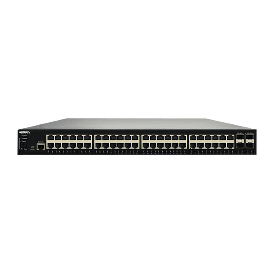
This quick start describes how to install, configure, and troubleshoot the NetVanta 1560-48, 48-port managed GbE switch. Figures 1 and 2 show the Front
and Rear Panel layouts of the switch.
■
"Installing the Switch"
on page 2
■
"Connecting to the Switch"
■
"Understanding the Status LEDs"
■
"Resetting the Switch"
on page 7
■
"Troubleshooting the Switch"
■
"Product Specifications"
on page 7
SYS
CONSOLE
LED
NetVanta 1560-48
SYSTEM
USB
RESET
RESET
Button
f
WARNING!
WARNING indicates a hazard which, if
not avoided, could result in death, injury
or serious property damage.
NetVanta 1560-48
48-port Managed GbE Switch
on page 5
on page 6
on page 7
Port
CONSOLE
1
2
3
4
5
6
7
8
9
10
11
12
f
CAUTION!
CAUTION indicates a hazard which, if not
avoided, could result in service interruption,
damage to the equipment, or minor property
damage.
Figure 1. Front Panel Layout
10/100/1000/2500
RJ-45
13
14
15
16
17
18
19
20
21
22
23
24
25
26
27
Port Status
LEDs
Figure 2. Rear Panel Layout
617101568F1-13A
28
29
30
31
32
33
34
35
36
37
38
39
40
41
42
43
AC Line: 100-240V 50-60Hz
g
NOTE
NOTES inform the user of additional, but
important, information or features.
April 2022
P/N: 17101568F1
1G/2.5G/10G
SFP+ Ports
44
45
46
47
48
49
50
51
52
Power Connection
AC Line: 100-240V 50-60Hz
Advertisement
Table of Contents

Subscribe to Our Youtube Channel
Related Manuals for ADTRAN NetVanta 1560-48


Summary of Contents for ADTRAN NetVanta 1560-48
- Page 1 Read all warnings, cautions, notes and installation instructions before installing or servicing this equipment. This quick start describes how to install, configure, and troubleshoot the NetVanta 1560-48, 48-port managed GbE switch. Figures 1 and 2 show the Front and Rear Panel layouts of the switch.
-
Page 2: Installing The Switch
CAUTION! The NetVanta 1560-48 is intended for indoor use only. Ethernet, PoE cables, and attached equipment are intended for use within the same building with equipotential bonding, and not intended to be placed in separate buildings or structures. Failure to deploy as described could result in permanent damage from lightning or other electrical events and voids the warranty. - Page 3 NOTE Rack mount brackets are a default accessory with the unit; spare brackets can be ordered through ADTRAN, part number: 1700519F1. Figure 4. Attaching Brackets to the Rack Post Mounting on a Desk or Shelf To mount the switch on a desk or shelf, complete the following steps.
- Page 4 3. Confirm that the power is connected properly. The SYSTEM LED should be ON (see “SYSTEM Status LED”). Figure 6. Connecting the AC Power Cord NOTE The installation of this product must comply with the national, state and local electrical code requirements, as applicable. The AC branch circuit overcurrent protection must be a fuse or circuit breaker rated 125 VAC, 20 Amps maximum or 250 VAC, 16 Amps maximum.
-
Page 5: Connecting To The Switch
Class 1 Laser modules from an ADTRAN approved vendor list (located on the ADTRAN website) should be installed in this product. ADTRAN cannot certify system integrity with other laser modules. The CDRH Laser Class emitted by the Fiber Optic Laser Module Component is Class I or 1 when installed in the end-product with the fiber-optic cable removed. -
Page 6: Understanding The Status Leds
c. Clean browser cookies and temporary Internet files. d. Check your PC settings again and repeat Step 2. 6. Enter the factory default username in the login page. Select Login to log into the switch. NOTE The factory default username of the switch is admin. The factory default password is password. Initial Switch Configuration Using CLI The CLI can be accessed using any one of the two console ports (USB &... -
Page 7: Resetting The Switch
2. This device must accept any interference received, including interference that may cause undesired operation. ■ Changes or modifications not expressly approved by ADTRAN could void the user's authority to operate this equipment. ■ Changes or modifications not expressly approved by ADTRAN will void the warranty. - Page 8 ADTRAN CUSTOMER CARE: Warranty: ADTRAN will replace or repair this product within the warranty period if it does not meet its published specifications or fails while in service. Warranty information can be From within the U.S. 1.888.423.8726 found online at www.adtran.com/warranty.
Need help?
Do you have a question about the NetVanta 1560-48 and is the answer not in the manual?
Questions and answers