Table of Contents
Advertisement
Quick Links
Quick Start
Overview
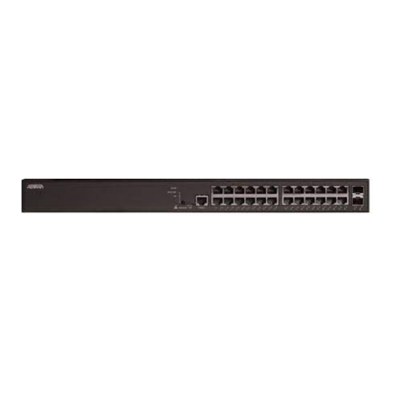
This quick start describes how to install, configure, and troubleshoot the NetVanta 1560-24-370W, 24-port Managed GbE 370W PoE+ Switch. Figures 1 and 2 show the Front
and Rear Panel layouts of the switch.
■
"Installing the Switch"
on page 1
■
■
on page 6
■
■
on page 7
■
on page 7
NetVanta 1560-24-370W
Installing the Switch
g
NOTE
Refer to the national, state and local electrical codes for the requirements for power, grounding, wiring, and installation methods.
f
WARNING!
Read all warnings, cautions, notes and installation instructions before installing or servicing this equipment.
Package Contents
■ NetVanta 1560-24-370W switch
■ AC power cord
■ DB-9 to RJ-45 cable
■ Micro-USB to USB cable
■ Four adhesive rubber feet
■ Mounting kit for rack mount (two brackets and eight screws)
■ Quick Start
NetVanta 1560-24-370W
24-port Managed GbE 370W PoE+ Switch
on page 5
on page 6
Figure 1. Front Panel Layout
LINK/ACT/SPD
SYS
Mode LED
LED
LNK/ACT/SPD
PoE
Mode LED
Figure 2. Rear Panel Layout
CONSOLE
Port
SYSTEM
PoE
USB
MODE/RESET
CONSOLE
1
2
3
4
5
6
MODE
Button
617101564PF2-13A
10/100/1000
RJ-45 with PoE+
7
8
9
10
11
12
13
14
15
16
17
18
19
Port Status
LEDs
AC Line: 100-240V 50-60Hz
Power Connection
AC Line: 100-240V 50-60Hz
May 2020
P/N: 17101564PF2
1G/10G
SFP+ Ports
20
21
22
23
24
25
26
Advertisement
Table of Contents

Related Manuals for ADTRAN NetVanta 1560-24-370W


Summary of Contents for ADTRAN NetVanta 1560-24-370W
- Page 1 Quick Start P/N: 17101564PF2 Overview This quick start describes how to install, configure, and troubleshoot the NetVanta 1560-24-370W, 24-port Managed GbE 370W PoE+ Switch. Figures 1 and 2 show the Front and Rear Panel layouts of the switch. ■ “Installing the Switch”...
- Page 2 CAUTION! The NetVanta 1560-24-370W is intended for indoor use only. Ethernet, PoE cables and attached equipment are intended for use within the same building with equipotential bonding, and not intended to be placed in separate buildings or structures. Failure to deploy as described could result in permanent damage from lightning or other electrical events and voids the warranty.
- Page 3 The NetVanta 1560-24-370W must be mounted in the face down orientation when wall mounted. Figure 6. Install Screws in the Wall and Hang the Switch on the Screws NOTE The wall mount brackets are not supplied with the unit and must be purchased separately from ADTRAN, part number 1700520F1. 617101564PF2-13A...
- Page 4 This product is intended for use with a Class 1 Laser module that complies with FDA 21 CFR 1040.10, 1040.11 and IEC 60825-1. For continued compliance with the above standards, only approved Class 1 laser modules from an ADTRAN approved vendor list (located on the ADTRAN website) should be installed in this product. ADTRAN cannot certify system integrity with other laser modules.
- Page 5 Initially Configuring the Switch The Switch can be configured by two methods: ■ Web based Graphical User Interface (GUI) ■ Command Line Interface (CLI) Initial Switch Configuration Using a Web Browser After powering up the switch for the first time, you can perform the initial switch configuration using a web browser. To begin with the initial configuration stage, you need to reconfigure your PC’s IP address and subnet mask to make sure the PC can communicate with the switch.
- Page 6 3. If using the Micro USB cable to connect the switch, check if the USB drivers are automatically installed in the PC. If not install manually. 4. Open a VT100 terminal session using the following settings: 115200 baud; 8 data bits; no parity bits; 1 stop bit; and no flow control. Press <Enter> to activate the CLI. admin password 5.
- Page 7 2. This device must accept any interference received, including interference that may cause undesired operation. ■ Changes or modifications not expressly approved by ADTRAN could void the user's authority to operate this equipment. ■ Changes or modifications not expressly approved by ADTRAN will void the warranty.
- Page 8 For inquiries, go to: ASE Command Reference Guide http://adtran.com/training Warranty: ADTRAN will replace or repair this product within the warranty period if it does not ADTRAN CUSTOMER CARE: meet its published specifications or fails while in service. Warranty information can be From within the U.S.
Need help?
Do you have a question about the NetVanta 1560-24-370W and is the answer not in the manual?
Questions and answers