Table of Contents
Advertisement
Quick Start
Overview
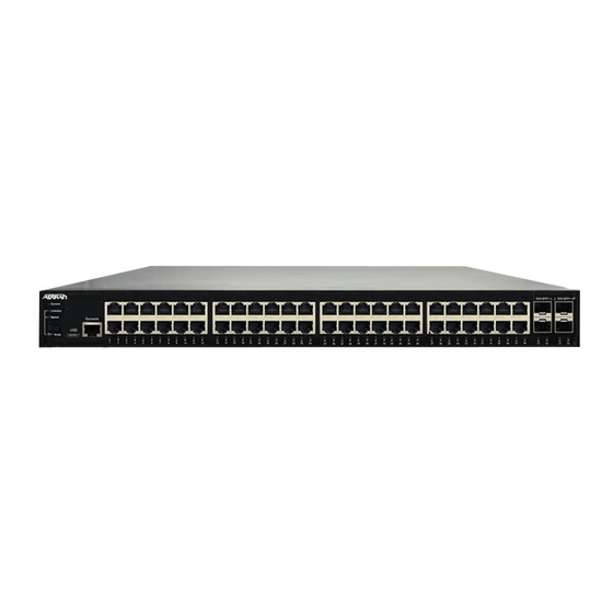
This quick start describes how to install, configure, and troubleshoot the NetVanta 1560-48-740W, 48-port Managed GbE 740W PoE+
Switch. Figures 1 and 2 show the Front and Rear Panel layouts of the switch.
■
"Installing the Switch"
on page 1
■
"Initially Configuring the Switch"
■
"Power Over Ethernet (PoE)"
■
"Understanding the Status LEDs"
■
"Using the MODE Button"
■
"Troubleshooting the Switch"
SYS
CONSOLE
LED
NetVanta 1560-48-740W
LINK/ACT/SPD
SYSTEM
LNK/ACT/SPD
Mode LED
PoE
MODE/RESET
PoE
MODE
Mode LED
Button
Installing the Switch
Package Contents
■
NetVanta 1560-48-740W switch
■
AC power cord
■
DB-9 to RJ-45 cable
■
Micro-USB to USB cable
■
Four adhesive rubber feet
■
Mounting kit (two brackets and eight screws)
■
Quick Start
f
WARNING!
The NetVanta 1560-48-740W is intended for indoor use only. Ethernet, PoE cables, and attached equipment are intended for use within
the same building with equipotential bonding, and not intended to be placed in separate buildings or structures. Failure to deploy as
described could result in permanent damage from lightning or other electrical events and voids the warranty.
NetVanta 1560-48-740W
48-port Managed GbE 740W PoE+ Switch
on page 4
on page 5
on page 6
on page 7
on page 7
Figure 1. Front Panel Layout
Port
USB
CONSOLE
1
2
3
4
5
6
7
8
9
10
11
12
Figure 2. Rear Panel Layout
10/100/1000
RJ-45 with PoE+
13
14
15
16
17
18
19
20
21
22
23
24
25
26
27
28
Port Status
LEDs
617108148PF2-13D
29
30
31
32
33
34
35
36
37
38
39
40
41
42
43
44
AC Line: 100-240V 50-60Hz
Power Connection
March 2020
P/N: 17108148PF2
1G/10G
SFP+ Ports
45
46
47
48
49
50
51
52
AC Line: 100-240V 50-60Hz
Advertisement
Table of Contents

Related Manuals for ADTRAN NetVanta 1560-48-740W


Summary of Contents for ADTRAN NetVanta 1560-48-740W
- Page 1 WARNING! The NetVanta 1560-48-740W is intended for indoor use only. Ethernet, PoE cables, and attached equipment are intended for use within the same building with equipotential bonding, and not intended to be placed in separate buildings or structures. Failure to deploy as...
-
Page 2: Installation Overview
3. Secure the brackets to the posts by inserting rack screws and tightening them with an appropriate screwdriver. Rack mount brackets are a default accessory with the unit; spare brackets can be ordered through ADTRAN, part number: 1700519F1. Figure 4. Attaching Brackets to the Rack Post... -
Page 3: Connect Ac Power
Mounting on a Desk or Shelf To mount the switch on a desk or shelf, complete the following steps. 1. Verify that the desk or shelf is sturdy enough to support the switch. 2. Attach the four adhesive rubber feet to the bottom of the switch. Figure 5. -
Page 4: Initially Configuring The Switch
This product is intended for use with a Class 1 Laser module that complies with FDA 21 CFR 1040.10, 1040.11 and IEC 60825-1. For continued compliance with the above standards, only approved Class 1 Laser modules from an ADTRAN approved vendor list (located online at www.adtran.com) should be installed in this product. -
Page 5: Power Over Ethernet (Poe)
■ Right-click on your local adapter and select Properties. ■ In the Local Area Connection Properties menu, highlight Internet Protocol Version 4 (TCP/IPv4). Then, select the Properties button. NOTE Be sure to record all your PC’s current IP settings to be able to restore them later. ■... -
Page 6: Understanding The Status Leds
Understanding the Status LEDs The LEDs on the front panel provide you with switch status checking and monitoring. The following section describes the three types of LEDs. SYSTEM Status LED The SYSTEM Status LED indicates if the switch is powered up correctly or if a system alarm has been triggered for troubleshooting. Color State Description... -
Page 7: Using The Mode Button
When PoE Mode LED Is Lit When the PoE Mode LED is lit, the PoE status is indicated by the LED behavior. Color State Description The port is enabled and supplying power to a connected device. An abnormal state, such as an overload status, has been detected in the switch. ... -
Page 8: Product Specifications
2. This device must accept any interference received, including interference that may cause undesired operation. ■ Changes or modifications not expressly approved by ADTRAN could void the user's authority to operate this equipment. NOTE This equipment has been tested and found to comply with the limits for a Class A digital device, pursuant to part 15 of the FCC Rules.
Need help?
Do you have a question about the NetVanta 1560-48-740W and is the answer not in the manual?
Questions and answers