Table of Contents
Advertisement
1702590G1
1702591G1/G2
1702544G1
1702545G1/G2
1700546G1#120
1700546G1#240
1700507F1
1700508F1
12008819E1
1700530F1
1700532F1
1700533F1
1700534F1
61702590G1-34E
April 2013
NetVanta 1534/1544 Series
Hardware Installation Guide
NetVanta 1534
NetVanta 1534P
NetVanta 1544
NetVanta 1544P
NetVanta 1544F with 120 VDC Power Supply
NetVanta 1544F with 240 VDC Power Supply
Wall Mounting Bracket
19-inch Dual Mounting Tray
CompactFlash
NetVanta 1131 RPS/EPS
NetVanta 1131 RPS Cable
NetVanta 1131 EPS Cable
NetVanta 1131 Dual Mounting Tray
, 1 GB
®
Advertisement
Table of Contents

Subscribe to Our Youtube Channel
Related Manuals for ADTRAN 1534/1544


Summary of Contents for ADTRAN 1534/1544
- Page 1 NetVanta 1534/1544 Series Hardware Installation Guide 1702590G1 NetVanta 1534 1702591G1/G2 NetVanta 1534P 1702544G1 NetVanta 1544 1702545G1/G2 NetVanta 1544P 1700546G1#120 NetVanta 1544F with 120 VDC Power Supply 1700546G1#240 NetVanta 1544F with 240 VDC Power Supply 1700507F1 Wall Mounting Bracket 1700508F1 19-inch Dual Mounting Tray...
- Page 2 To the Holder of the Manual The contents of this manual are current as of the date of publication. ADTRAN reserves the right to change the contents without prior notice. In no event will ADTRAN be liable for any special, incidental, or consequential damages or for commercial losses even if ADTRAN has been advised thereof as a result of issue of this publication.
- Page 3 NetVanta 1500 Series Hardware Installation Guide Conventions Conventions Notes provide additional useful information. Cautions signify information that could prevent service interruption or damage to the equipment. Warnings provide information that could prevent injury or endangerment to human life. 61702590G1-34E Copyright © 2013 ADTRAN, Inc.
- Page 4 These units contain no user-serviceable parts. They should only be serviced by qualified service personnel. Additional safety guidelines, such as Waste Electrical and Electronic Equipment (WEEE), are given in the document NetVanta Safety and Regulatory Information available at https:/ /supportforums.adtran.com. Save These Important Safety Instructions Copyright © 2013 ADTRAN, Inc. 61702590G1-34E...
- Page 5 Denial of Service (DoS) attacks, loss or theft of data, and the unauthorized or illegal use of said equipment. ADTRAN OFFERS NO WARRANTIES, EITHER EXPRESSED OR IMPLIED, REGARDING THE PREVENTION, DETECTION, OR DETERRENCE OF TOLL FRAUD, NETWORKING ATTACKS, OR UNAUTHORIZED, ILLEGAL, OR IMPROPER USE OF ADTRAN EQUIPMENT OR SOFTWARE.
- Page 6 Service and Warranty NetVanta 1500 Series Hardware Installation Guide Copyright © 2013 ADTRAN, Inc. 61702590G1-34E...
-
Page 7: Table Of Contents
Connector Pin Definitions..........47 61702590G1-34E Copyright © 2013 ADTRAN, Inc. - Page 8 Table of Contents NetVanta 1500 Series Hardware Installation Guide Copyright © 2013 ADTRAN, Inc. 61702590G1-34E...
- Page 9 Figure 13. NetVanta 1534/1544 Wallmount Installation ........
- Page 10 List of Figures NetVanta 1500 Series Hardware Installation Guide Copyright © 2013 ADTRAN, Inc. 61702590G1-34E...
- Page 11 Table A-3. SFP Slot Pinouts ............48 61702590G1-34E Copyright © 2013 ADTRAN, Inc.
- Page 12 List of Tables NetVanta 1500 Series Hardware Installation Guide Copyright © 2013 ADTRAN, Inc. 61702590G1-34E...
-
Page 13: Introduction
Ethernet (PoE)), the NetVanta 1544, the NetVanta 1544P (PoE), and the NetVanta 1544F. In this document, the term NetVanta 1534/1544 means all of the units collectively. If a statement only applies to one particular switch, the text refers to that switch individually. -
Page 14: Physical Descriptions
PHYSICAL DESCRIPTIONS NetVanta 1534 Series The NetVanta 1534 Series is a Layer 3 Lite managed switch. The entire series runs ADTRAN Operating System (AOS), is managed through an EIA-232 CONSOLE port (DB-9), Telnet session, or Web-based graphical user interface (GUI), and is RoHS compliant (telecommunications exemption). The NetVanta 1534 Series units are described in the following sections. -
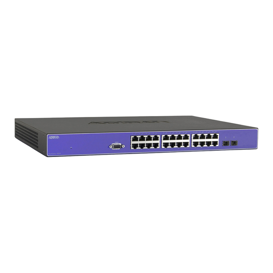
Page 15: Figure 1. Netvanta 1534 Front Panel Layout
After unpacking the unit, inspect it for possible shipping damage. If the equipment has been damaged in transit, immediately file a claim with the carrier and contact ADTRAN Customer Service (refer to the Support page on the ADTRAN website at http://www.adtran.com/support). -
Page 16: Figure 2. Netvanta 1534 Rear Panel Layout
The CONSOLE interface is an EIA-232 serial port (DCE) that provides local management and configuration (via a DB-9 female connector). Refer to Table A-1 on page 47 for pinouts. Connection directly to an external modem requires a cross-over cable. Copyright © 2013 ADTRAN, Inc. 61702590G1-34E... -
Page 17: Figure 3. Netvanta 1534P Front Panel Layout
VCID. LED Mode Switch (Future Release) The LED mode switch is located on the left side of the unit and is used to toggle Ports 1 through 48 between link/activity and VCID display modes. 61702590G1-34E Copyright © 2013 ADTRAN, Inc. -
Page 18: Figure 4. Netvanta 1534P Rear Panel Layout
RPS. Power Connection The rear panel has a power input to the AC universal power supply. Please refer to Supplying Power to the Unit on page 36 for connection details. Copyright © 2013 ADTRAN, Inc. 61702590G1-34E... -
Page 19: Netvanta 1544 Series
As well as the four 1000/2500Base-X SFP slots, the NetVanta 1544F units support 24 100/1000Base-X SFP interfaces that are accessed via fiber or copper using industry standard SFP modules. For a list of supported SFP modules, visit the ADTRAN website at http://www.adtran.com. -
Page 20: Figure 5. Netvanta 1544 Front Panel Layout
After unpacking the unit, inspect it for possible shipping damage. If the equipment has been damaged in transit, immediately file a claim with the carrier and contact ADTRAN Customer Service (refer to the Support page on the ADTRAN website at http://www.adtran.com/support). -
Page 21: Figure 6. Netvanta 1544 Rear Panel Layout
25 through 28, support both 1000Base-X and 1000/2500Base-X SFP modules, and their status LEDs are located on the front panel of the unit. Refer to Table A-3 on page 48 for pinouts. 61702590G1-34E Copyright © 2013 ADTRAN, Inc. -
Page 22: Figure 7. Netvanta 1544P Front Panel Layout
The PoE LED is located on the left side of the unit and indicates that the port LEDs are displaying PoE status. VCID LED (Future Release) The VCID LED is located on the left side of the unit and indicates that the port LEDs are displaying VCID. Copyright © 2013 ADTRAN, Inc. 61702590G1-34E... -
Page 23: Figure 8. Netvanta 1544P Rear Panel Layout
NetVanta 1544F Front Panel Design The NetVanta 1544F front panel is shown below. Table 1 on page 25 describes all of the LEDs, and Appendix A on page 47 shows the connector pinouts. 61702590G1-34E Copyright © 2013 ADTRAN, Inc. -
Page 24: Figure 9. Netvanta 1544F Front Panel Layout
64 MB to 1 GB. Power Connection The rear panel has a power input to the AC universal power supply. Please refer to Supplying Power to the Unit on page 36 for connection details. Copyright © 2013 ADTRAN, Inc. 61702590G1-34E... -
Page 25: Led Descriptions
The device has not been admitted to the ActivChassis and the port LED (1 through 8) that corresponds to the unit’s assigned VCID value is lit. Ports 25 through 28 are always in LINK/ACT mode. 61702590G1-34E Copyright © 2013 ADTRAN, Inc. -
Page 26: Product Specifications
Number of collisions • Number of errors Spanning Tree Support • 802.1D spanning tree • 802.1w rapid spanning tree Link Aggregation • 802.3ad link aggregation • Support for six trunk groups, 8 ports per group Copyright © 2013 ADTRAN, Inc. 61702590G1-34E... - Page 27 Dimensions NetVanta 1534P/1544P: 1.7-inch H x 17.2-inch W x 10.0-inch D • Internal AC power NetVanta 1534/1544: 100 to 250 VAC, 50/60 Hz, 40 W maximum • Internal AC power NetVanta 1534P/1544P: 110 to 240 VAC, 50/60 Hz, 370 W maximum •...
- Page 28 • EN 61000-3-3 • ICES 003 Class A • EN 300 386 • AS/NZS CISPR22 Class A • UL/CUL 60950-1 • EN 60950-1 • IEC 60950-1 • AS/NZS 60950-1 • RoHS compliant (telecommunications exemption) Copyright © 2013 ADTRAN, Inc. 61702590G1-34E...
-
Page 29: Unit Installation
To prevent electrical shock, do not install equipment in a wet location or during a lightning storm. • The NetVanta 1534/1544 Series is intended to be installed, maintained, and serviced by qualified service personnel only and should be installed in a restricted access location as described in UL/IEC 60950-1. -
Page 30: Tools Required
ADTRAN Support Community. Mounting Options The NetVanta 1534/1544 Series units can be installed in rackmount, wallmount, or tabletop configurations. The following sections provide step-by-step instructions for rack mounting and wall mounting. Rack Mounting the NetVanta 1534/1544 Series The NetVanta 1534/1544 Series are 1U-high, rack-mountable units that can be installed into a 19-inch equipment rack with the mounting brackets that are shipped with the units. -
Page 31: Figure 11. Netvanta 1534/1544 Rack Mounting Brackets And Kensington Lock Slot
Apply power to the unit (refer to Supplying Power to the Unit on page 36). The NetVanta 1534/1544 Series units have a Kensington lock slot that accepts a lock and cable security device (see Figure 11). Consult the manual shipped with your Kensington lock for installation instructions. -
Page 32: Figure 12. Dual Mounting Tray
Apply power to the units (refer to Supplying Power to the Unit on page 36). The NetVanta 1534/1544 Series units have a Kensington lock slot that accepts a lock and cable security device (see Figure 11). Consult the manual shipped with your Kensington lock for installation instructions. - Page 33 Wall Mounting the NetVanta 1534/1544 Series Units By following these instructions exactly, the NetVanta 1534/1544 Series units can be safely mounted on the wall. For instructions on wall mounting NetVanta 1534 and NetVanta 1544 units, see the table below and...
-
Page 34: Figure 13. Netvanta 1534/1544 Wallmount Installation
Unit Installation NetVanta 1534/1544 Series Figure 13. NetVanta 1534/1544 Wallmount Installation Copyright © 2013 ADTRAN, Inc. 61702590G1-34E... -
Page 35: Figure 14. Netvanta 1534P/1544P/1544F Wallmount Installation
(see Figure 14). Proceed to the steps given in Supplying Power to the Unit on page Figure 14. NetVanta 1534P/1544P/1544F Wallmount Installation 61702590G1-34E Copyright © 2013 ADTRAN, Inc. -
Page 36: Supplying Power To The Unit
AC power source. Installing a CompactFlash Card CompactFlash slot supports only ADTRAN-provided 1 GB CompactFlash cards (P/N 1200819E1). Follow these instructions when installing a card. The CompactFlash card is hot-swappable and can be inserted or removed while power is applied to the unit. -
Page 37: Netvanta 1131 Rps/Eps
After unpacking the unit, inspect it for possible shipping damage. If the equipment has been damaged in transit, immediately file a claim with the carrier and contact ADTRAN Customer Service (refer to the Support page on the ADTRAN website at http://www.adtran.com/support). -
Page 38: Netvanta 1131 Front Panel Design
The STAT LEDs for RPS1, RPS2, and RPS3 are located on the left side of the unit and indicate status of the RPS connections. NetVanta 1131 Rear Panel Design The NetVanta 1131 rear panel is shown below. POWER RPS1 RPS2 RPS3 Figure 17. NetVanta 1131 Rear Panel Layout Copyright © 2013 ADTRAN, Inc. 61702590G1-34E... -
Page 39: Led Behaviors
There is a valid connection to the switch. Installing the NetVanta 1131 RPS/EPS The instructions and guidelines provided in the following sections cover hardware installation topics, such as mounting options and supplying power to the NetVanta 1131. 61702590G1-34E Copyright © 2013 ADTRAN, Inc. -
Page 40: Rack Mounting The Netvanta 1131
This equipment incorporates double pole/neutral fusing. If the neutral fuse opens and the line fuse does not open, voltage could still be present in the unit. Line and neutral are provided with fuses for overcurrent protection. Copyright © 2013 ADTRAN, Inc. 61702590G1-34E... -
Page 41: Figure 18. Rack Mounting The Netvanta 1131 Using The Brackets
Proceed to the steps given in Connecting the NetVanta 1131 and the NetVanta Switch on page Mid-mount 2-inch Mount Front Mount Figure 18. Rack Mounting the NetVanta 1131 Using the Brackets 61702590G1-34E Copyright © 2013 ADTRAN, Inc. -
Page 42: Figure 19. Rack Mounting The Netvanta 1131 Using The Dual Mounting Tray
Insert the provided screws through the tabs into the units securing them with a screwdriver. Proceed to the steps given in Connecting the NetVanta 1131 and the NetVanta Switch on page Figure 19. Rack Mounting the NetVanta 1131 Using the Dual Mounting Tray Copyright © 2013 ADTRAN, Inc. 61702590G1-34E... -
Page 43: Wall Mounting The Netvanta 1131
(see Figure 20). Proceed to the steps given in Powering the NetVanta 1131 and the NetVanta Switch on page Figure 20. Wall Mounting the NetVanta 1131 61702590G1-34E Copyright © 2013 ADTRAN, Inc. -
Page 44: Connecting The Netvanta 1131 And The Netvanta Switch
To remove an RPS or EPS cable from the unit, pinch the sides of the connector and pull gently to release it from the receptacle. Proceed to Powering the NetVanta 1131 and the NetVanta Switch on page Copyright © 2013 ADTRAN, Inc. 61702590G1-34E... -
Page 45: Powering The Netvanta 1131 And The Netvanta Switch
ADTRAN Support Community. For details on the command line interface (CLI), refer to the AOS Command Reference Guide. All other related documents are also available online at http://supportforums.adtran.com. 61702590G1-34E Copyright © 2013 ADTRAN, Inc. - Page 46 NetVanta 1131 RPS/EPS NetVanta 1534/1544 Series Copyright © 2013 ADTRAN, Inc. 61702590G1-34E...
-
Page 47: Appendix A. Connector Pin Definitions
Unused Table A-2. 1000Base-T Gigabit Ethernet Port Pinouts Name Description TRD0+ Transmit/Receive Positive TRD0- Transmit/Receive Negative TRD1+ Transmit/Receive Positive TRD2+ Transmit/Receive Positive TRD2- Transmit/Receive Negative TRD1- Transmit/Receive Negative TRD3+ Transmit/Receive Positive TRD3- Transmit/Receive Negative 61702590G1-34E Copyright © 2013 ADTRAN, Inc. -
Page 48: Table A-3. Sfp Slot Pinouts
Appendix A. Connector Pin Definitions NetVanta 1500 Series Hardware Installation Guide Table A-3. SFP Slot Pinouts Name Name TX_FAULT RX_DAT- TX_DISABLE RX_DAT+ I2C_SDA I2C_SCL VddR MOD_DEF(0) VddT RATESEL RX_LOS TX_DAT+ TX_DAT- Copyright © 2013 ADTRAN, Inc. 61702590G1-34E...
Need help?
Do you have a question about the 1534/1544 and is the answer not in the manual?
Questions and answers