Table of Contents
Advertisement
1700568F1
1700569F1
1700460F1
1700462F1
1700470F1
1700471F1
1700473F1
1700530F1
1700532F1
1700533F1
1700534F1
61700568F1-34D
April 2013
NetVanta 1600 Series
Gigabit Ethernet Switch
Hardware Installation Guide
NetVanta 1638
NetVanta 1638P
NetVanta 120 W AC Power Supply
NetVanta 500 W PoE Power Supply
NetVanta Dual Stacking XIM
NetVanta Dual SFP+ XIM
NetVanta Dual SFP XIM
NetVanta 1131 RPS/EPS
NetVanta 1131 RPS Cable
NetVanta 1131 EPS Cable
NetVanta 1131 Dual Mounting Tray
Advertisement
Table of Contents

Related Manuals for ADTRAN NetVanta 1638


Summary of Contents for ADTRAN NetVanta 1638
- Page 1 NetVanta 1600 Series Gigabit Ethernet Switch Hardware Installation Guide 1700568F1 NetVanta 1638 1700569F1 NetVanta 1638P 1700460F1 NetVanta 120 W AC Power Supply 1700462F1 NetVanta 500 W PoE Power Supply 1700470F1 NetVanta Dual Stacking XIM 1700471F1 NetVanta Dual SFP+ XIM 1700473F1...
- Page 2 To the Holder of the Manual The contents of this manual are current as of the date of publication. ADTRAN reserves the right to change the contents without prior notice. In no event will ADTRAN be liable for any special, incidental, or consequential damages or for commercial losses even if ADTRAN has been advised thereof as a result of issue of this publication.
- Page 3 NetVanta 1600 Series Hardware Installation Guide Conventions Conventions Notes provide additional useful information. Cautions signify information that could prevent service interruption or damage to the equipment. Warnings provide information that could prevent injury or endangerment to human life. 61700568F1-34D Copyright © 2013 ADTRAN, Inc.
- Page 4 These units contain no user-serviceable parts. They should only be serviced by qualified service personnel. Additional safety guidelines, such as Waste Electrical and Electronic Equipment (WEEE), are given in the document NetVanta Safety and Regulatory Information available online at http://supportforums.adtran.com. Save These Important Safety Instructions Copyright © 2013 ADTRAN, Inc. 61700568F1-34D...
-
Page 5: Fcc Radio Frequency Interference Statement
Department of Communications. Cet appareil numérique respecte les limites de bruits radioelectriques applicables aux appareils numériques de Class A prescrites dans la norme sur le materiel brouilleur: “Appareils Numériques,” NMB-003 edictee par le ministre des Communications. 61700568F1-34D Copyright © 2013 ADTRAN, Inc. - Page 6 Denial of Service (DoS) attacks, loss or theft of data, and the unauthorized or illegal use of said equipment. ADTRAN OFFERS NO WARRANTIES, EITHER EXPRESSED OR IMPLIED, REGARDING THE PREVENTION, DETECTION, OR DETERRENCE OF TOLL FRAUD, NETWORKING ATTACKS, OR UNAUTHORIZED, ILLEGAL, OR IMPROPER USE OF ADTRAN EQUIPMENT OR SOFTWARE.
-
Page 7: Table Of Contents
NetVanta 1638 ........ - Page 8 Table of Contents NetVanta 1600 Series Hardware Installation Guide Copyright © 2013 ADTRAN, Inc. 61700568F1-34D...
- Page 9 NetVanta 1638 Front Panel Layout ........
- Page 10 List of Figures NetVanta 1600 Series Hardware Installation Guide Copyright © 2013 ADTRAN, Inc. 61700568F1-34D...
- Page 11 Table A-2. 1000Base-T Gigabit Ethernet Port Pinouts ........43 61700568F1-34D Copyright © 2013 ADTRAN, Inc.
- Page 12 List of Tables NetVanta 1600 Series Hardware Installation Guide Copyright © 2013 ADTRAN, Inc. 61700568F1-34D...
-
Page 13: Introduction
INTRODUCTION The NetVanta 1600 Series Gigabit Switches include the NetVanta 1638 and the NetVanta 1638P (Power over Ethernet (PoE)). In this document, the term NetVanta 1600 means all of the units collectively. If a statement only applies to one particular switch, the text refers to that switch individually. -
Page 14: Physical Descriptions
The NetVanta 1600 Series is housed in a 1U-high rack-mountable metal enclosure that includes field replaceable power supplies and fans. The NetVanta 1638 is shipped with the NetVanta 120 W AC power supply (P/N 1700460F1) installed that provides +12 VDC and a redundant power supply (RPS) connector. The NetVanta 1638P is shipped with the NetVanta 500 W PoE power supply (P/N 1700462F1) installed that provides +12 VDC and +50 VDC and both an RPS and an extended power supply (EPS) connector. -
Page 15: Netvanta 1600 Series Shipping Contents
After unpacking the unit, inspect it for possible shipping damage. If the equipment has been damaged in transit, immediately file a claim with the carrier and contact ADTRAN Customer Service (refer to the Support page on the ADTRAN website at http://www.adtran.com/support). -
Page 16: Netvanta 1638
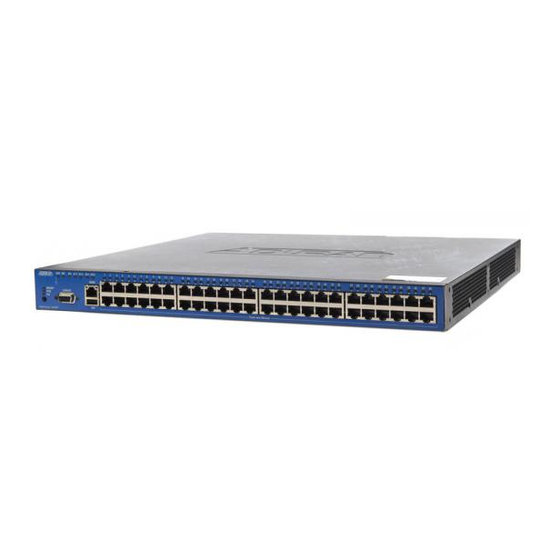
Physical Descriptions NetVanta 1600 Series Hardware Installation Guide NetVanta 1638 Front Panel Design The NetVanta 1638 front panel is shown below. Table 1 on page 21 describes all of the LEDs, and Appendix A on page 43 shows the connector pinouts. -
Page 17: Figure 2. Netvanta 1638 Rear Panel Layout
Status LEDs for each stacked pair of interfaces are located directly over the interfaces. See Table A-2 on page 43 for pinouts. Rear Panel Design The NetVanta 1638 rear panel is shown below. ® 120 WATT POWER SUPPLY 1700460F1 AC INPUT... -
Page 18: Netvanta 1638P
The VCID LED is located on the left side of the unit and indicates that the port LEDs are displaying VCID. PoE LED The PoE LED is located on the left side of the unit and indicates that the port LEDs are displaying PoE status. Copyright © 2013 ADTRAN, Inc. 61700568F1-34D... -
Page 19: Figure 4. Netvanta 1638P Rear Panel Layout
NetVanta 500 W PoE Power Supply The rear panel houses the field replaceable NetVanta 500 W PoE power supply. For information on replacing the power supply, refer to Replacing the Power Supply on page 61700568F1-34D Copyright © 2013 ADTRAN, Inc. - Page 20 EPS status. Power Connection The NetVanta 500 W PoE power supply has a power input to the AC universal power supply. Refer to Supplying Power to the Unit on page 31 for connection details. Copyright © 2013 ADTRAN, Inc. 61700568F1-34D...
-
Page 21: Led Descriptions
LED (1 through 8) that corresponds to the unit’s assigned VCID value is lit. For more information on LED behaviors in VCID mode, refer to the ActivChassis in AOS configuration guide available on the ADTRAN Support Forum. 61700568F1-34D Copyright © 2013 ADTRAN, Inc. -
Page 22: Product Specifications
• LLDP-Media Endpoint Discovery (LLDP-MED) • Ping • Cable diagnostics Front Panel Status LEDs • Power status • LAN: link, activity • VCID • Redundant power supply • Extended power supply (NetVanta 1638P only) Copyright © 2013 ADTRAN, Inc. 61700568F1-34D... - Page 23 Wi-Fi access controller for centralized management of NetVanta wireless access points (APs) • Supports 24 APs Environment • Operating Temperature: 0°C to 50°C (32°F to 122°F) • Storage Temperature: -20°C to 70°C (-4°F to 158°F) • Relative Humidity: Up to 95 percent, noncondensing 61700568F1-34D Copyright © 2013 ADTRAN, Inc.
- Page 24 Dimensions (NetVanta 1638): 1.72-inch H x 17.22-inch W x 16.75-inch D • Dimensions (NetVanta 1638P): 1.72-inch H x 17.22-inch W x 16.75-inch D • Internal AC power (NetVanta 1638): 110 to 240 VAC, 1.5 A, 50/60 Hz • Internal AC power (NetVanta 1638P):110 to 240 VAC, 5.7A, 50/60 Hz •...
-
Page 25: Option Modules
Shipments of the NetVanta Dual SFP+ XIM include the following items: • Dual SFP+ XIM • Quick start guide NetVanta Dual SFP XIM (1700473F1) Shipments of the NetVanta Dual SFP XIM include the following items: • Dual SFP XIM • Quick start guide 61700568F1-34D Copyright © 2013 ADTRAN, Inc. -
Page 26: Xaui Interface Modules
XAUI Interface Modules NetVanta Dual Stacking XIM (P/N 1700470F1) The NetVanta Dual Stacking XIM (shown in Figure 5) provides high-speed connectivity between two ADTRAN 10 Gbps capable devices. ® STACKING XIM 1700470F1 Figure 5. NetVanta Dual Stacking XIM Features and Specifications... -
Page 27: Figure 6. Netvanta Dual Sfp+ Xim
• RoHS compliant Only approved 'Class 1 Laser Product’ SFP and SFP+ modules from ADTRAN's approved vendor list should be installed in this product. ADTRAN cannot certify system integrity with other laser modules. Please refer to the ADTRAN website at www.adtran.com... -
Page 28: Figure 7. Netvanta Dual Sfp Xim
UL/CUL 60950-1 • RoHS compliant Only approved 'Class 1 Laser Product’ SFP modules from ADTRAN's approved vendor list should be installed in this product. ADTRAN cannot certify system integrity with other laser modules. Please refer to the ADTRAN website at www.adtran.com... -
Page 29: Unit Installation
ADTRAN's for this purpose will void the user's warranty. • PoE cables are intended for intrabuilding use only. Connecting an ADTRAN PoE unit directly to PoE cables that run outside the building in which the unit is housed will void the user's warranty and could create a fire or shock hazard. -
Page 30: Tools Required
• Reliable grounding of rack-mounted equipment should be maintained. Particular attention should be given to supply connections other than direct connections to the branch circuit (e.g., use of power strips). Copyright © 2013 ADTRAN, Inc. 61700568F1-34D... -
Page 31: Supplying Power To The Unit
Supplying Power to the Unit The NetVanta 1638 units come equipped with a field replaceable universal 110 to 240 VAC, 1.5 A, 50/60 Hz power supply (NetVanta 120 W AC Power Supply, P/N 1700460F1). The NetVanta 1638P units come equipped with a field replaceable universal 110 to 240 VAC, 5.7A, 50/60 Hz power supply (NetVanta 500 W PoE Power... -
Page 32: Figure 8. Installing The Power Supply
Reconnect the power cord(s). ® 120 WATT POWER SUPPLY 1700460F1 AC INPUT RPS - 12VDC CAUTION DISCONNECT ALL POWER CABLES PRIOR TO REMOVAL OF POWER SUPPLY Pull Tab Figure 8. Installing the Power Supply Copyright © 2013 ADTRAN, Inc. 61700568F1-34D... -
Page 33: Installing Xaui Interface Modules
XIMs are hot swappable. However, they will not function until the power is cycled or a manual reload of AOS is performed on the main unit. Refer to the AOS Command Reference Guide (ADTRAN’s Support Forum article 2219) at http://supportforums.adtran.com for more information on the reload command. 61700568F1-34D... -
Page 34: Netvanta 1131 Rps/Eps
After unpacking the unit, inspect it for possible shipping damage. If the equipment has been damaged in transit, immediately file a claim with the carrier and contact ADTRAN Customer Service (refer to the Support page on the ADTRAN website at http://www.adtran.com/support). -
Page 35: Netvanta 1131 Front Panel Design
The STAT LEDs for RPS1, RPS2, and RPS3 are located on the left side of the unit and indicate status of the RPS connections. NetVanta 1131 Rear Panel Design The NetVanta 1131 rear panel is shown below. POWER RPS1 RPS2 RPS3 Figure 11. NetVanta 1131 Rear Panel Layout 61700568F1-34D Copyright © 2013 ADTRAN, Inc. -
Page 36: Led Behaviors
Power is being provided to the associated port. Amber (flashing) A fault condition exists on the associated port. EPS CONN There is no connection to the switch. Green (solid) There is a valid connection to the switch. Copyright © 2013 ADTRAN, Inc. 61700568F1-34D... -
Page 37: Installing The Netvanta 1131 Rps/Eps
This equipment incorporates double pole/neutral fusing. If the neutral fuse opens and the line fuse does not open, voltage could still be present in the unit. Line and neutral are provided with fuses for overcurrent protection. 61700568F1-34D Copyright © 2013 ADTRAN, Inc. -
Page 38: Figure 12. Rack Mounting The Netvanta 1131 Using The Brackets
Proceed to the steps given in Connecting the NetVanta 1131 and the NetVanta Switch on page Mid-mount 2-inch Mount Front Mount Figure 12. Rack Mounting the NetVanta 1131 Using the Brackets Copyright © 2013 ADTRAN, Inc. 61700568F1-34D... -
Page 39: Figure 13. Rack Mounting The Netvanta 1131 Using The Dual Mounting Tray
Insert the provided screws through the tabs into the units securing them with a screwdriver. Proceed to the steps given in Connecting the NetVanta 1131 and the NetVanta Switch on page Figure 13. Rack Mounting the NetVanta 1131 Using the Dual Mounting Tray 61700568F1-34D Copyright © 2013 ADTRAN, Inc. -
Page 40: Wall Mounting The Netvanta 1131
(see Figure 14). Proceed to the steps given in Powering the NetVanta 1131 and the NetVanta Switch on page Figure 14. Wall Mounting the NetVanta 1131 Copyright © 2013 ADTRAN, Inc. 61700568F1-34D... -
Page 41: Connecting The Netvanta 1131 And The Netvanta Switch
To remove an RPS or EPS cable from the unit, pinch the sides of the connector and pull gently to release it from the receptacle. Proceed to Powering the NetVanta 1131 and the NetVanta Switch on page 61700568F1-34D Copyright © 2013 ADTRAN, Inc. -
Page 42: Powering The Netvanta 1131 And The Netvanta Switch
ADTRAN’s Support Forum For details on the CLI, refer to the AOS Command Reference Guide (article 2219). All other related documents are also available online on ADTRAN’s Support Forum. Copyright © 2013 ADTRAN, Inc. 61700568F1-34D... -
Page 43: Appendix A. Connector Pin Definitions
Unused Table A-2. 1000Base-T Gigabit Ethernet Port Pinouts Name Description TRD0+ Transmit/Receive Positive TRD0- Transmit/Receive Negative TRD1+ Transmit/Receive Positive TRD2+ Transmit/Receive Positive TRD2- Transmit/Receive Negative TRD1- Transmit/Receive Negative TRD3+ Transmit/Receive Positive TRD3- Transmit/Receive Negative 61700568F1-34D Copyright © 2013 ADTRAN, Inc. - Page 44 Appendix A. Connector Pin Definitions NetVanta 1600 Series Hardware Installation Guide Copyright © 2013 ADTRAN, Inc. 61700568F1-34D...
Need help?
Do you have a question about the NetVanta 1638 and is the answer not in the manual?
Questions and answers