Table of Contents
Advertisement
Quick Links
Quick Start
Overview
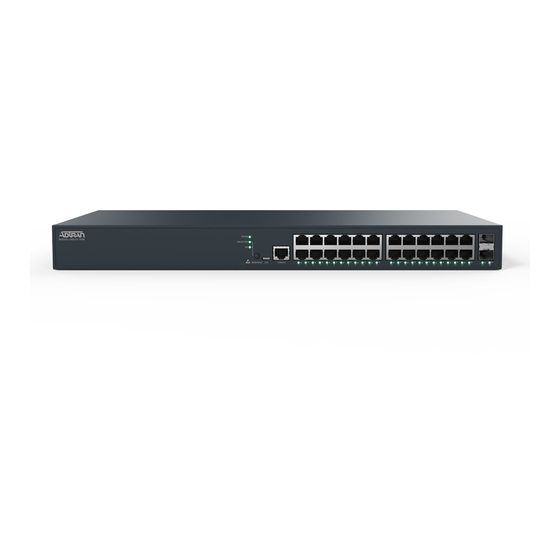
This quick start describes how to install, configure, and troubleshoot the NetVanta 1560-24-740W, 24-port Managed GbE 740W PoE+ Switch. Figures 1
and 2 show the Front and Rear Panel layouts of the switch.
■
"Installing the Switch"
on page 1
■
"Initially Configuring the Switch"
■
"Power Over Ethernet (PoE)"
■
"Understanding the Status LEDs"
■
"Using the MODE Button"
on page 7
■
"Troubleshooting the Switch"
NetVanta 1560-24-740W
Installing the Switch
Package Contents
■
NetVanta 1560-24-740W switch
■
AC power cord
■
DB-9 to RJ-45 cable
■
Micro-USB to USB cable
■
Four adhesive rubber feet
■
Mounting kit for rack mount (two brackets and eight screws)
■
Quick Start
f
WARNING!
The NetVanta 1560-24-740W is intended for indoor use only. Ethernet, PoE cables and attached equipment are intended for use within the same building
with equipotential bonding, and not intended to be placed in separate buildings or structures. Failure to deploy as described could result in permanent
damage from lightning or other electrical events and voids the warranty.
NetVanta 1560-24-740W
24-port Managed GbE 740W PoE+ Switch
on page 4
on page 6
on page 6
on page 7
Figure 1. Front Panel Layout
LINK/ACT/SPD
SYS
Mode LED
LED
SYSTEM
LNK/ACT/SPD
PoE
Mode LED
Figure 2. Rear Panel Layout
CONSOLE
Port
PoE
USB
MODE/RESET
CONSOLE
1
2
3
4
5
6
7
MODE
Button
617108124PF2-13D
10/100/1000
RJ-45 with PoE+
8
9
10
11
12
13
14
15
16
17
18
19
20
Port Status
LEDs
AC Line: 100-240V 50-60Hz
Power Connection
AC Line: 100-240V 50-60Hz
March 2020
P/N: 17108124PF2
1G/10G
SFP+ Ports
21
22
23
24
25
26
Advertisement
Table of Contents

Subscribe to Our Youtube Channel
Related Manuals for ADTRAN NetVanta 1560-24-740W


Summary of Contents for ADTRAN NetVanta 1560-24-740W
- Page 1 WARNING! The NetVanta 1560-24-740W is intended for indoor use only. Ethernet, PoE cables and attached equipment are intended for use within the same building with equipotential bonding, and not intended to be placed in separate buildings or structures. Failure to deploy as described could result in permanent...
- Page 2 3. Secure the brackets to the posts by inserting rack screws and tightening them with an appropriate screwdriver. NOTE Rack mount brackets are a default accessory with the unit; spare brackets can be ordered through ADTRAN, part number: 1700519F1. Figure 4. Attaching Brackets to the Rack Post...
- Page 3 The NetVanta 1560-24-740W must be mounted in the face down orientation when wall mounted. Figure 6. Install Screws in the Wall and Hang the Switch on the Screws NOTE The wall mount brackets are not supplied with the unit and must be purchased separately from ADTRAN, part number 1700520F1. 617108124PF2-13D...
- Page 4 This product is intended for use with a Class 1 Laser module that complies with FDA 21 CFR 1040.10, 1040.11 and IEC 60825-1. For continued compliance with the above standards, only approved Class 1 laser modules from an ADTRAN approved vendor list (llocated online at www.adtran.com) should be installed in this product.
- Page 5 To begin with the initial configuration stage, you need to reconfigure your PC’s IP address and subnet mask to make sure the PC can communicate with the switch. After changing PC’s IP address (for example, 10.10.10.250), then you can access the web interface of the switch using the switch’s default IP address as shown below.
- Page 6 Complete the following steps: 1. Connect a Micro USB cable to the micro USB CONSOLE port or connect a DB-9 to RJ-45 serial cable to the RJ-45 CONSOLE port. 2. If using a Micro USB cable, connect the other end of the USB cable to a USB port on the PC. If using an RJ-45 serial cable, connect the other end to the serial terminal on the PC.
- Page 7 Color State Description The port is enabled, has established a link to a connected device, and the connection speed is 10 Gbps. Flashing The port is transmitting/receiving packets, and the connection speed is 10 Gbps. The port is enabled, has established a link to connected device, and the connection speed is 1 Gbps. SFP+ Ports ...
- Page 8 2. This device must accept any interference received, including interference that may cause undesired operation. ■ Changes or modifications not expressly approved by ADTRAN could void the user's authority to operate this equipment. NOTE This equipment has been tested and found to comply with the limits for a Class A digital device, pursuant to part 15 of the FCC Rules. These limits are designed to provide reasonable protection against harmful interference when the equipment is operated in a commercial environment.
Need help?
Do you have a question about the NetVanta 1560-24-740W and is the answer not in the manual?
Questions and answers