Table of Contents
Advertisement
Quick Links
Quick Start
Overview
f
WARNING!
Read all warnings, cautions, notes and installation instructions before installing or servicing this equipment.
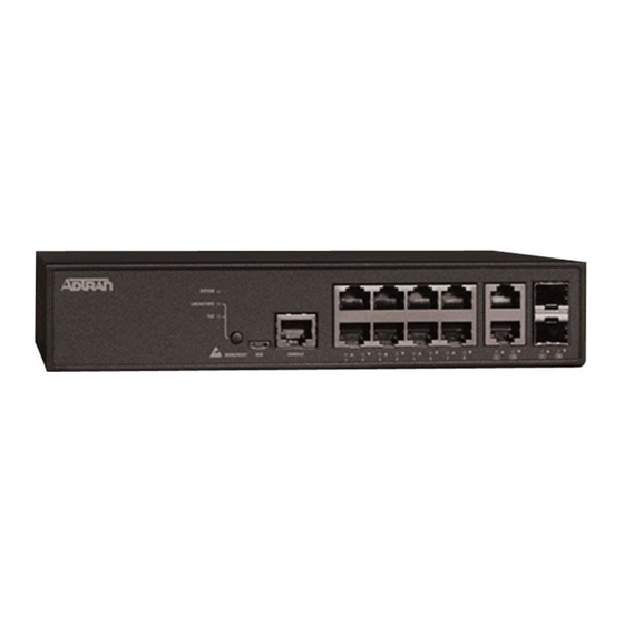
This quick start describes how to install, configure, and troubleshoot the NetVanta 1560-08, 8-port managed GbE switch. Figures 1 and 2 show the Front
and Rear Panel layouts of the switch.
■
"Installing the Switch"
on page 2
■
"Connecting to the Switch"
on page 5
■
"Understanding the Status LEDs"
■
"Resetting the Switch"
on page 7
■
"Troubleshooting the Switch"
■
"Product Specifications"
on page 7
f
WARNING!
WARNING indicates a hazard which, if
not avoided, could result in death, injury
or serious property damage.
NetVanta 1560-08
8-port Managed GbE Switch
on page 6
on page 7
Figure 1. Front Panel Layout
NetVanta 1560-08
f
CAUTION!
CAUTION indicates a hazard which, if not
avoided, could result in service interruption,
damage to the equipment, or minor property
damage.
SYS
CONSOLE
10/100/1000
LED
Port
RJ-45 Ports
SYSTEM
USB
RESET
CONSOLE
1
2
3
4
5
RESET
Port Status
Button
Figure 2. Rear Panel Layout
AC Line: 100-240V 50-60Hz
617101561F1-13A
100/1000 RJ-45/SFP
Combo Ports
6
7
8
9
10
9
10
LEDs
Power Connection
AC Line: 100-240V 50-60Hz
g
NOTE
NOTES inform the user of additional, but
important, information or features.
April 2022
P/N: 17101561F1
Advertisement
Table of Contents

Subscribe to Our Youtube Channel
Related Manuals for ADTRAN NetVanta 1560-08


Summary of Contents for ADTRAN NetVanta 1560-08
- Page 1 Read all warnings, cautions, notes and installation instructions before installing or servicing this equipment. This quick start describes how to install, configure, and troubleshoot the NetVanta 1560-08, 8-port managed GbE switch. Figures 1 and 2 show the Front and Rear Panel layouts of the switch.
-
Page 2: Installing The Switch
CAUTION! The NetVanta 1560-08 is intended for indoor use only. Ethernet cables and attached equipment are intended for use within the same building with equipotential bonding, and not intended to be placed in separate buildings or structures. Failure to deploy as described could result in permanent damage from lightning or other electrical events and voids the warranty. - Page 3 3. Have an assistant hold the unit in position, with the oval holes in the brackets aligned with the mounting holes in the rack posts, as you insert two rack screws and tighten them with the appropriate screw driver. Figure 4. Attaching Brackets to the Rack Post Mounting the Switch on a Desk or Shelf To mount the switch on a desk or shelf, complete the following steps.
- Page 4 Figure 7. Attaching the Switch to the Wall CAUTION! The NetVanta 1560-08 must be mounted in the face-down orientation when wall mounted. Supplying Power to the Switch To connect the AC power cord to the switch, complete the following steps.
-
Page 5: Connecting To The Switch
Class 1 Laser modules from an ADTRAN approved vendor list (located on the ADTRAN website) should be installed in this product. ADTRAN cannot certify system integrity with other laser modules. The CDRH Laser Class emitted by the Fiber Optic Laser Module Component is Class I or 1 when installed in the end-product with the fiber-optic cable removed. -
Page 6: Understanding The Status Leds
d. Right-click on your local adapter and select Properties. e. In the Local Area Connection Properties menu, highlight Internet Protocol Version 4 (TCP/IPv4). Then, select the Properties button. NOTE Be sure to record all your PC’s current IP settings to be able to restore them later. Select the radio button Use the following IP address and enter in the IP address for the PC (e.g., any IP address not in use, and between 10.10.10.2 and 10.10.10.254), subnet mask (e.g., 255.255.255.0). -
Page 7: Resetting The Switch
This device may not cause harmful interference. ■ 2. This device must accept any interference received, including interference that may cause undesired operation. ■ Changes or modifications not expressly approved by ADTRAN could void the user's authority to operate this equipment. 617101561F1-13A... - Page 8 ADTRAN CUSTOMER CARE: Warranty: ADTRAN will replace or repair this product within the warranty period if it does not meet its published specifications or fails while in service. Warranty information can be From within the U.S. 1.888.423.8726 found online at www.adtran.com/warranty.
Need help?
Do you have a question about the NetVanta 1560-08 and is the answer not in the manual?
Questions and answers