Table of Contents
Advertisement
Quick Links
Quick Start
Overview
f
WARNING!
Read all warnings, cautions, notes and installation instructions before installing or servicing this equipment.
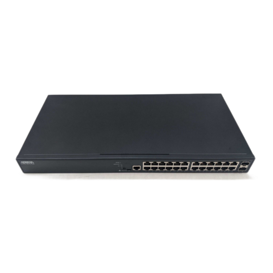
This quick start describes how to install, configure, and troubleshoot the NetVanta 1560-24, 24-port managed GbE switch. Figures 1 and 2 show the Front
and Rear Panel layouts of the switch.
■
"Installing the Switch"
on page 2
■
"Connecting to the Switch"
■
"Understanding the Status LEDs"
■
"Resetting the Switch"
on page 8
■
"Troubleshooting the Switch"
■
"Product Specifications"
on page 8
NetVanta 1560-24
f
WARNING!
WARNING indicates a hazard which, if
not avoided, could result in death, injury
or serious property damage.
NetVanta 1560-24
24-port Managed GbE Switch
on page 5
on page 7
on page 8
f
CAUTION!
CAUTION indicates a hazard which, if not
avoided, could result in service interruption,
damage to the equipment, or minor property
damage.
Figure 1. Front Panel Layout
SYS
CONSOLE
LED
Port
SYSTEM
RESET
USB
CONSOLE
1
2
3
4
5
6
RESET
Button
Figure 2. Rear Panel Layout
617101564F1-13A
10/100/1000/2500
RJ-45
7
8
9
10
11
12
13
14
15
16
17
18
19
Port Status
LEDs
AC Line: 100-240V 50-60Hz
Power Connection
AC Line: 100-240V 50-60Hz
g
NOTE
NOTES inform the user of additional, but
important, information or features.
July 2022
P/N: 17101564F1
1G/2.5G/10G
SFP+ Ports
20
21
22
23
24
25
26
Advertisement
Table of Contents

Subscribe to Our Youtube Channel
Related Manuals for ADTRAN NetVanta 1560-24


Summary of Contents for ADTRAN NetVanta 1560-24
- Page 1 Read all warnings, cautions, notes and installation instructions before installing or servicing this equipment. This quick start describes how to install, configure, and troubleshoot the NetVanta 1560-24, 24-port managed GbE switch. Figures 1 and 2 show the Front and Rear Panel layouts of the switch.
-
Page 2: Installing The Switch
CAUTION! The NetVanta 1560-24 is intended for indoor use only. Ethernet, PoE cables and attached equipment are intended for use within the same building with equipotential bonding, and not intended to be placed in separate buildings or structures. Failure to deploy as described could result in permanent damage from lightning or other electrical events and voids the warranty. - Page 3 NOTE Rack mount brackets are a default accessory with the unit; spare brackets can be ordered through ADTRAN, part number: 1700519F1. Figure 4. Attaching Brackets to the Rack Post Mounting on a Desk or Shelf To mount the switch on a desk or shelf, complete the following steps.
-
Page 4: Supplying Power To The Switch
The NetVanta 1560-24 must be mounted in the face-down orientation when wall mounted. NOTE The wall mount brackets are not supplied with the unit and must be purchased separately from ADTRAN, part number 1700520F1. Supplying Power to the Switch To connect the AC power cord to the switch, complete the following steps. -
Page 5: Installing Sfp Modules
This product is intended for use with a Class 1 Laser module that complies with FDA 21 CFR 1040.10, 1040.11 and IEC 60825-1. For continued compliance with the above standards, only approved Class 1 laser modules from an ADTRAN approved vendor list (located on the ADTRAN website) should be installed in this product. - Page 6 To begin with the initial configuration stage, you need to reconfigure your PC’s IP address and subnet mask to make sure the PC can communicate with the switch. After changing PC’s IP address (for example, 10.10.10.250), then you can access the web interface of the switch using the switch’s default IP address as shown below.
-
Page 7: Understanding The Status Leds
Initial Switch Configuration Using CLI The CLI can be accessed using any one of the two console ports (USB & RJ-45) available in the switch. To establish the connection to the console port, the following are needed: ■ PC with VT100 terminal emulation software ■... -
Page 8: Resetting The Switch
2. This device must accept any interference received, including interference that may cause undesired operation. ■ Changes or modifications not expressly approved by ADTRAN could void the user's authority to operate this equipment. ■ Changes or modifications not expressly approved by ADTRAN will void the warranty. - Page 9 ADTRAN CUSTOMER CARE: Warranty: ADTRAN will replace or repair this product within the warranty period if it does not meet its published specifications or fails while in service. Warranty information can be From within the U.S. 1.888.423.8726 found online at www.adtran.com/warranty.
Need help?
Do you have a question about the NetVanta 1560-24 and is the answer not in the manual?
Questions and answers