Western Digital Ultrastar Serv60+8 User Manual
Hide thumbs
Also See for Ultrastar Serv60+8:
- User manual (406 pages) ,
- Manual (51 pages) ,
- Recommended rack configurations (33 pages)

Related Manuals for Western Digital Ultrastar Serv60+8


Summary of Contents for Western Digital Ultrastar Serv60+8
- Page 1 User Guide Ultrastar Serv60+8 Regulatory Model: H4060-S December 2018 Rev. 1.3 1ET1110 ™ Long Live Data | www.hgst.com...
-
Page 2: Table Of Contents
Revision History....................7 Copyright......................8 Chapter 1 Overview..................9 1.1 Ultrastar Serv60+8 Description............9 1.2 System Architecture Overview............10 System Level Block Diagram............11 1.4 Ultrastar Serv60+8 Specification Summary........12 Ultrastar Serv60+8 Layout...............15 1.6 List of Customer Replaceable Units (CRUs)........17 1.7 Supported Operating Systems............19 LEDs....................20 1.8.1 Front and Rear IO LEDs...............20 1.8.2... - Page 3 Contents User Guide 3.2.1 IOM Specifications...............38 3.2.2 IOM Layout...................39 3.2.3 IOM Blank Description..............39 3.3 PSU Description................40 3.3.1 PSU Specifications...............40 3.3.2 PSU Layout..................41 3.4 System Fan Description..............42 Rails Description................42 3.5.1 Rails Specifications..............43 3.5.2 Rails Layout..................43 3.5.3 Rear Cover Alignment Bracket Description........44 CMA Description................44 3.6.1 CMA Specifications..............45...
- Page 4 Contents User Guide 4.8 CPU and Heat Sink Module Replacement........99 Heat Sink Replacement..............128 4.10 M.2 Replacement.................161 4.11 Add-in Card Replacement............178 4.12 CMA Replacement...............196 4.13 Rails Replacement...............201 4.14 Chassis Replacement..............225 Chapter 5 System Management............277 5.1 Storage Subsystem Firmware Upgrade.........277 5.1.1 Downloading Firmware from the Support Portal......277 5.1.2 Linux Upgrade Preparation............279 5.1.3...
- Page 5 Contents User Guide 5.3.3 Security Features...............313 5.3.3.1 Enabling Security Settings.............314 5.3.4 Network Settings................317 5.3.4.1 Configuring the IPv4 Network Settings........317 5.3.4.2 Configuring the IPv6 Network Settings........320 5.3.4.3 Configuring VLAN Settings.............323 5.3.5 BMC Web GUI Firmware............324 5.3.5.1 Updating BMC Web GUI Firmware........324 5.3.5.2 Updating the Server BMC Firmware Using Redfish OOBM..329 5.3.6...
- Page 6 8.5 Taiwan Warning Label Statement, Class A ITE......348 Chapter 9 Points of Contact..............349 Appendix A Site and System Operation Requirements......350 Power Requirements..............350 Supported Operating Systems............350 A.3 List of Supported Server Components..........351 A.4 Ultrastar Serv60+8 Rack Requirements........352 A.4.1 Compatible Hardware Configuration..........354 ESD....................355 A.6 Enclosure Cooling................355 A.7 Host Connectivity................356...
-
Page 7: Revision History
Revision History User Guide Revision History Date Revision Comment June 2018 Revision 1.0 Initial Release July 2018 Revision 1.1 Added the following sections: • DIMM Replacement on page 72 • CPU and Heat Sink Module Replacement on page 99 • Heat Sink Replacement on page 128 •... -
Page 8: Copyright
The following paragraph does not apply to the United Kingdom or any country where such provisions are inconsistent with local law: HGST a Western Digital company PROVIDES THIS PUBLICATION "AS IS" WITHOUT WARRANTY OF ANY KIND, EITHER EXPRESS OR IMPLIED, INCLUDING, BUT NOT LIMITED TO, THE IMPLIED WARRANTIES OF MERCHANTABILITY OR FITNESS FOR A PARTICULAR PURPOSE. -
Page 9: Chapter 1 Overview
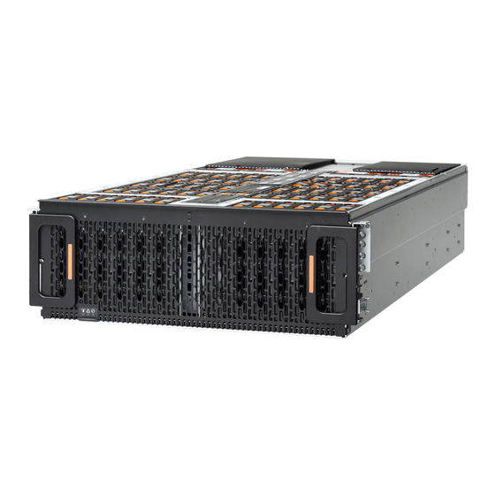
The Ultrastar Serv60+8 is a 4U form factor, high density, rack-mounted storage enclosure that is capable of hosting up to 60 HDD SAS or SATA drives. The maximum data storage capacity of the Ultrastar Serv60+8 is 720TB using 12TB HGST Ultrastar He12 HDDs plus an additional 61.44 TB using HGST Ultrastar SS300 SSDs in the system SSD slots. -
Page 10: System Architecture Overview
1.2 System Architecture Overview Storage Subsystem Overview The Ultrastar Serv60+8 IOM uses a cascaded expander design to allow for connection to all 60 HDD drives. The minimum configuration comes with two of the six PCIe slots pre-populated with a combination of internal SAS HBAs and RAID adapters that act as an interconnect between the server subsystem and the storage subsystem by connecting to the system SSDs and the IOM. -
Page 11: System Level Block Diagram
System Level Block Diagram 1.3 System Level Block Diagram The following image shows the system block diagram for the Ultrastar Serv60+8. The block diagram is split into two, one for the storage subsystem and one for the server subsystem. Figure 2: System Block Diagram for the Storage Subsystem... -
Page 12: Ultrastar Serv60+8 Specification Summary
Overview User Guide Ultrastar Serv60+8 Specification Summary 1.4 Ultrastar Serv60+8 Specification Summary Table 1: Environmental Specification Summary Specification Non-Operational Operational Temperature -40°C to 70°C 5°C to 35°C Temperature Gradient 30°C per hour maximum 20°C per hour maximum Temperature De-rating 1°C per 300m above 3000m 1°C per 300m above 900m... - Page 13 Typical Inrush Current (per PSU) Caution: The Ultrastar Serv60+8 can only be plugged into highline. If the unit is plugged into lowline, the PSU will report a "Critical" state when status pages are queried using SES. In this case, the enclosure will power up, but the drives will not.
- Page 14 Overview User Guide Ultrastar Serv60+8 Specification Summary Specification Non-Operational Operational Required Rack Width 450mm with (17.72in.) with 465mm (18.31in.) ± 1.5mm nominal hole spacing. See EIA-310 Rack Standard Required Rack Depth 1200 mm (47.24in.) of usable rack space, frame to frame...
-
Page 15: Ultrastar Serv60+8 Layout
Overview User Guide Ultrastar Serv60+8 Layout 1.5 Ultrastar Serv60+8 Layout Figure 4: Front and Rear Product Layout Table 5: Front and Rear Component Identification Number Component Enclosure Handles PSUs Rear IO Ports Chassis Cover Rails... - Page 16 Overview User Guide Ultrastar Serv60+8 Layout The following is an image of the layout of the major system components inside the Ultrastar Serv60+8. Figure 5: Component Layout Figure 6: Rear IO Ports...
-
Page 17: List Of Customer Replaceable Units (Crus)
1.6 List of Customer Replaceable Units (CRUs) The following table lists the replaceable components and their part numbers. Table 6: List of Replaceable Components Component Part Number Ultrastar Serv60+8 Chassis with Single IOM and PSUs 1EX1801 1EX1828 IOM Blank 1EX0431... - Page 18 Overview User Guide List of Customer Replaceable Units (CRUs) Component Part Number ® Intel I350-T4V2 NIC 1EX1770 ® Intel X520-DA2 NIC 1EX1267 ® Intel X520-SR2 NIC 1EX1772 ® Intel X540-T2 NIC 1EX1270 ® Intel X710-DA2 NIC 1EX1268 ® Intel X710-DA4 NIC 1EX1771 QLogic QLE2692 NIC 1EX1774...
-
Page 19: Supported Operating Systems
Overview User Guide Supported Operating Systems 1.7 Supported Operating Systems Table 7: Compatible Operating Systems Operating System Microsoft Windows Server 2012 R2 x64 Microsoft Windows Server 2016 R1 x64 RedHat Red Hat Enterprise Linux (x86_64) 7.4 RedHat Red Hat Enterprise Linux (x86_64) 7.3 RedHat Red Hat Enterprise Linux (x86_64) 7.2 Ubuntu Ubuntu Server 16.04 Kernel 4.4... -
Page 20: Leds
Front and Rear IO LEDs The Ultrastar Serv60+8 has three LEDs on the front and three on the rear that mirror each other and provide general status. This allows the status of the enclosure to be visible from either side of the rack. -
Page 21: Iom Leds
Overview User Guide LEDs 1.8.2 IOM LEDs The IOM has three LEDs, one each for power, fault, and identification. Figure 9: IOM LEDs Table 9: IOM LED Identification LED Name Color Behavior IOM Identification Blue Blink @ 1 Hz – Blinks only when IOM Identification has been activated. -
Page 22: Psu Led
Overview User Guide LEDs 1.8.3 PSU LED The PSU has a single multi-function LED. See the table below for a detailed functional description. Figure 10: PSU LEDs Table 10: PSU LED Identification LED Name Color Behavior PSU Multi-function LED Green Solid –... -
Page 23: Drive Assembly Led
Overview User Guide LEDs 1.8.4 Drive Assembly LED The HDD drive assemblies themselves do not contain an LED. However, there is an amber multi-function LED located on the drive carrier that has three distinct states, one for a fault condition, one for identification, and off. -
Page 24: List Of Compatible Drives
Overview User Guide List of Compatible Drives The SSD drive assemblies also have a multifunction LED. Figure 12: SSD Assembly LED Table 12: SSD LED Identification LED Name Color Behavior Drive Multi-function LED Amber Solid – Drive Fault Blinking @ 1 Hz – Drive Identify Off –... - Page 25 Overview User Guide List of Compatible Drives Drive Type Interface Sector Size Encryption Volume Part Number HGST Ultrastar DC HC310 SATA 6Gb/s 512e 1EX1188 w/ 3.5 in. drive carrier HGST Ultrastar DC HC320 SAS 12Gb/s 1EX1221 w/ 3.5 in. drive carrier HGST Ultrastar DC HC320 SAS 12Gb/s 1EX1220...
- Page 26 Overview User Guide List of Compatible Drives Drive Type Interface Sector Size Encryption Volume Part Number HGST Ultrastar He10 SAS 12Gb/s 512e 10TB 1EX0486 w/ 3.5 in. drive carrier HGST Ultrastar He10 SAS 12Gb/s 512e TCG-FIPS 10TB 1EX1341 w/ 3.5 in. drive carrier HGST Ultrastar He10 SATA 6Gb/s 10TB...
- Page 27 Overview User Guide List of Compatible Drives Drive Type Interface Sector Size Encryption Volume Part Number HGST Ultrastar He12 SATA 6Gb/s 12TB 1EX1012 w/ 3.5 in. drive carrier HGST Ultrastar He12 SATA 6Gb/s 12TB 1EX1011 w/ 3.5 in. drive carrier HGST Ultrastar He12 SATA 6Gb/s 512e...
- Page 28 Overview User Guide List of Compatible Drives Drive Type Interface Drive Encryption Volume Part Writes Number HGST Ultrastar SS300 SAS 12Gb/s ME-10DW/D 400GB 1EX1159 w/ 2.5 in. drive carrier HGST Ultrastar SS300 SAS 12Gb/s ME-10DW/D 400GB 1EX1346 w/ 2.5 in. drive carrier HGST Ultrastar SS300 SAS 12Gb/s ME-10DW/D...
- Page 29 Overview User Guide List of Compatible Drives Drive Type Interface Drive Encryption Volume Part Writes Number HGST Ultrastar SS300 SAS 12Gb/s RI-3DW/D 800GB 1EX1348 w/ 2.5 in. drive carrier HGST Ultrastar SS300 SAS 12Gb/s RI-3DW/D TCG-FIPS 800GB 1EX1349 w/ 2.5 in. drive carrier Sandisk Cloudspeed Ultra Gen.
- Page 30 Overview User Guide List of Compatible Drives Drive Type Interface Drive Encryption Volume Part Writes Number Sandisk Cloudspeed Ultra Gen. II SATA 6Gb/s RI-1.8DW/D 400GB 1EX1294 w/ 3.5 in to 2.5 in drive carrier HGST Ultrastar SS200 SAS 12Gb/s RI-1DW/D 480GB 1EX1318 w/ 3.5 in to 2.5 in drive carrier...
- Page 31 Overview User Guide List of Compatible Drives Drive Type Interface Drive Encryption Volume Part Writes Number HGST Ultrastar SS200 SAS 12Gb/s RI-3DW/D 1.6TB 1EX1304 w/ 3.5 in to 2.5 in drive carrier HGST Ultrastar SS200 SAS 12Gb/s RI-3DW/D 1.6TB 1EX1784 w/ 3.5 in to 2.5 in drive carrier HGST Ultrastar SS200 SAS 12Gb/s...
- Page 32 Overview User Guide List of Compatible Drives Drive Type Interface Drive Encryption Volume Part Writes Number HGST Ultrastar SS300 SAS 12Gb/s RI-10DW/D 1.6TB 1EX1310 w/ 3.5 in to 2.5 in drive carrier HGST Ultrastar SS300 SAS 12Gb/s ME-10DW/D TCG-FIPS 1.6TB 1EX1786 w/ 3.5 in to 2.5 in drive carrier Sandisk Cloudspeed Ultra Gen.
- Page 33 Overview User Guide List of Compatible Drives Drive Type Form Factor Interface Encryption Volume Part Number SanDisk X600 M.2 2280 SATA 6Gb/s 1EX1577 HGST Ultrastar SA210 M.2 2280 SATA 6Gb/s 1.92TB 1EX1581 SanDisk X600 M.2 2280 SATA 6Gb/s 1EX1573 SanDisk X600 M.2 2280 SATA 6Gb/s 1EX1578...
-
Page 34: Chapter 2 System Management Overview
There are also two out-of-band interfaces that can be accessed through BMC that are integrated into the system via the RJ45 port on the Ultrastar Serv60+8. The interface is a GUI that is accessible via the BMC management port on the rear of the enclosure. The BMC is also accessible using IPMI and using the Redfish RESTful interface. -
Page 35: Oobm Management Overview
2.2 OOBM Management Overview The Ultrastar Serv60+8 uses an implementation of DMTF Redfish for out-of-band system management. All the SES enclosure information can be obtained through the out-of-band management port using RESTful API calls to the management port over HTTPS. -
Page 36: Chapter 3 Component Overviews
The chassis is the primary housing that contains and connects all of the system components that comprise the Ultrastar Serv60+8. The chassis is comprised of the drive bay that contains all of the system data storage drives and a number of other bays that contain the major system components such as the PSUs and IOM. -
Page 37: Chassis Layout
Component Overviews User Guide Chassis Description 3.1.2 Chassis Layout Figure 14: Layout Table 18: Exterior Components Number Feature PSU Bays • Top bay: PSU A • Bottom bay: PSU B Server IO Chassis Handles IOM Bay SSD Drive Bays HDD Drive Bays System Fan Slots System Fan Slots (center channel) The chassis has a removable cover that encloses the internal system components and ensures proper airflow. -
Page 38: Iom Description
Component Overviews User Guide IOM Description 3.2 IOM Description Figure 15: Overview Image The IOM provides system data connectivity through 4 Mini-SAS HD ports each capable of four 12Gbps SAS connections. The IOM is installed into the central bay from the top of the Chassis and connect to the drive board. -
Page 39: Iom Layout
Component Overviews User Guide IOM Description 3.2.2 IOM Layout Figure 16: Layout Rear Front Table 20: Exterior Components Number Feature IOM Handle Latch Release Internal IO Connector Card Edge Power Receptacle Internal IO Connector 3.2.3 IOM Blank Description Figure 17: Overview Image The IOM Blank is a placeholder component that is used to fill the unused IOM slot. -
Page 40: Psu Description
3.3 PSU Description Figure 18: Overview Image Ultrastar Serv60+8 contains redundant 2000W Power Supply Units (PSU). Each PSU requires an input voltage of between 200 - 240 VAC. The PSUs are 80 PLUS Platinum certified, and utilize C14 power cable receptacles. -
Page 41: Psu Layout
Component Overviews User Guide PSU Description 3.3.2 PSU Layout Figure 19: Layout Rear/Front Table 22: Exterior Components Number Feature Internal Connector C14 Power Receptacle Latch Release Lever Handle... -
Page 42: System Fan Description
Figure 21: Overview Image The Ultrastar Serv60+8 is installed into a rack using a toolless-attach rail system. The rails are a two-piece system with one rail that attaches directly to the chassis called the inner rail and the other that attaches to the rack. -
Page 43: Rails Specifications
Component Overviews User Guide Rails Description to vertical rack rails that should be set between 32 in.-36 in. The toolless design means that an installer can attach these rails to a rack without any tools which simplifies installation. Once they are attached, they can be secured with the included M5 screws and washers. -
Page 44: Rear Cover Alignment Bracket Description
The rear cover alignment brackets are designed to keep the top cover of the chassis in the rack while extending the Ultrastar Serv60+8 out of the rack for servicing. The rear cover alignment brackets will attach to the rear vertical rack rails and rest on top of the toolless rail system. -
Page 45: Cma Specifications
The design of the Ultrastar Serv60+8 CMA is a single-arm design that supports all of the cabling used in the enclosure. The cables are secured to the arm by plastic clips called baskets that can be opened at the top to adjust, add, or remove cables. -
Page 46: Drive Assembly Description
Component Overviews User Guide Drive Assembly Description 3.7 Drive Assembly Description Figure 26: Overview Image The Drive Assembly is comprised of two parts: the storage drive and the drive carrier. The carrier attaches to the exterior of the data storage drive and caddies the drive into the enclosure. It stabilizes the motion of the drive into the drive bay so that the drive properly mounts onto the drive board. -
Page 47: Drive Assembly Layout
Component Overviews User Guide Drive Assembly Description 3.7.2 Drive Assembly Layout Figure 27: Layout Side Bottom Table 28: Exterior Components Number Feature Latches Latch Release IO and Power Connectors Drive Carrier Disk Drive... -
Page 48: Drive Carrier Description
The 2.5" carrier assembly is used to adapt a 2.5" form factor data storage drive to the 3.5" drive slots in the Ultrastar Serv60+8 drive bays. This allows the enclosure to accommodate high speed SSD drives as its primary data storage medium. The carrier operates by utilizing an innovative clamping mechanism. The 2.5"... - Page 49 Component Overviews User Guide Drive Assembly Description 1. Locate the release clips on the rear and press them inward to release the clamp. Figure 29: Clamp Release (clamp shown in blue for visual clarity) 2. Slide the clamp in the direction shown in the following image to loosen it from the drive. Be sure not to slide too far as this will allow the clamp to fall from from the carrier body and it will have to be reinstalled.
-
Page 50: Drive Blank Description
Component Overviews User Guide Drive Assembly Description 4. Slide the clamp back toward the drive making sure that the two plastic pins on the side of the drive properly install into the drive screwholes. If these pins are not seated properly, unlatch the clamp and retry. Figure 31: Clamp Pins (clamp shown in blue for visual clarity) 3.7.4 Drive Blank Description... - Page 51 Component Overviews User Guide Drive Assembly Description When the number of drives that are used in a row is less then the total that are necessary to fill that row, the 3.5" drive blank is used to fill out the row in place of actual drives. Figure 32: 3.5"...
-
Page 52: System Ssd Description
The system SSD drives are located in the center channel inside the enclosure. These drives can be used in the same fashion as the 3.5" drives populating the major data storage bays in the Ultrastar Serv60+8. They are accessible via the storage subsystem architecture through SES or through the Redfish OOBM. -
Page 53: Chapter 4 Part Replacement
Part Replacement User Guide Part Replacement Service Window Chapter 4 Part Replacement 4.1 Part Replacement Service Window The following table contains a time required and a replacement window related to each hot swappable replacement part within the enclosure. The time required for replacement is the expected amount of time it requires to replace the part. - Page 54 Part Replacement User Guide IOM Replacement 1. Grasp both handles at the front of the enclosure and pull with even pressure to extend the chassis out of the rack until it is stopped by the safety latches. The safety latches will prevent the enclosure from coming out of the rack completely and the cover will remain in the rack attached to the rear alignment brackets.
- Page 55 Part Replacement User Guide IOM Replacement b) Grasp both handles, one handle in each hand, and lift evenly with both hands to ensure the IOM comes out straight. This will prevent any damage to the pins on the internal connectors. Figure 37: Removing IOM 4.
- Page 56 Part Replacement User Guide IOM Replacement b) Ensure that the handles on the IOM are not latched. To unlatch them, press the latch release in the direction shown in the following image. Figure 38: Unlatching IOM Handles c) Align the IOM with the empty slot on the top of the chassis so that the arrow on the IOM latch release is facing toward the side shown in the following image.
-
Page 57: Psu Replacement
Part Replacement User Guide PSU Replacement d) Slowly lower the IOM into the empty slot while being careful to keep it level. Do not to force it. Figure 39: Installing the IOM e) When the IOM is lowered fully, apply light pressure with both hands evenly on the IOM body, not the handles, to seat the IOM in the connector. - Page 58 Part Replacement User Guide PSU Replacement a) Unlatch the CMA at the elbow connector by pressing the blue release button to unlatch the connector from the rail. Figure 40: Unlatching a CMA Connector b) Swing the CMA away from the enclosure. c) The arm should be extended away from the enclosure as shown in the following example.
- Page 59 Part Replacement User Guide PSU Replacement 3. Detach the retention clip from the PSU cable. Figure 42: Cable Retention Mechanism 4. Remove the power cable from the faulty PSU. 5. Uninstall the PSU. a) Grasp the release lever and the metal handle in a downward pinching motion to release the latching mechanism.
- Page 60 Part Replacement User Guide PSU Replacement b) Slide the PSU into the slot until it seats fully into the chassis. Figure 44: Installing the PSU c) Plug the power cable into the receptacle at the back of the PSU. d) Loop the retention clip on the PSU cables around the cable and pinch it until the clip catches and locks in place.
-
Page 61: System Fan Replacement
Part Replacement User Guide System Fan Replacement e) Slide the retention clip forward until it stops near the cable connector. Doing this will ensure that the retention clip functions properly in the event the cable is pulled on for some reason. Figure 46: Cinching Cable Retention Clip 8. - Page 62 Part Replacement User Guide System Fan Replacement 4. Uninstall the internal System Fan. a) Lift the System Fan flap and insert a finger into the service hole on the top of the System Fan and pull up to release the latch. Figure 48: Lift the System Fan Flap Figure 49: Unlatching System Fan...
- Page 63 Part Replacement User Guide System Fan Replacement b) Use the handle to pull evenly on the component to remove it from the enclosure. Figure 50: Removing System Fans 5. Remove the new System Fan from its packaging. 6. Install the System Fan. a) Lift the System Fan flap and look inside the empty slot that will receive the System Fan and orient the System Fan so that the connector on the bottom of the fan is on the proper side.
-
Page 64: Drive Assembly Replacement
Part Replacement User Guide Drive Assembly Replacement b) Lower the fan down into the empty slot. Do not force it. Figure 52: Installing a System Fan c) When the fan is fully inserted and the connectors are mated properly, close the housing cover clip as shown in the following image. - Page 65 Part Replacement User Guide Drive Assembly Replacement 1. Grasp both handles at the front of the enclosure and pull with even pressure to extend the chassis out of the rack until it is stopped by the safety latches. The safety latches will prevent the enclosure from coming out of the rack completely and the cover will remain in the rack attached to the rear alignment brackets.
- Page 66 Part Replacement User Guide Drive Assembly Replacement b) Insert a finger and a thumb into the latch release and pinch to unlatch the Drive Assembly. Figure 56: Unlatch Drive Carrier (IOM Not Shown)
- Page 67 Part Replacement User Guide Drive Assembly Replacement c) Lift the Drive Assembly free from the enclosure. Figure 57: Removing Drive Assembly 4. Remove the new Drive Assembly from its packaging. 5. Install the Drive Assembly. a) Ensure that the enclosure has been pulled out of the rack until the rail latches engage.
- Page 68 Part Replacement User Guide Drive Assembly Replacement b) Find the LED pointer on the top of the drive carrier. This pointer should point toward the front of the unit as shown in the following image. Figure 58: LED Pointer Orientation REAR FRONT...
-
Page 69: System Ssd Replacement
Part Replacement User Guide System SSD Replacement c) Align the drive with the empty slot that will receive it. Lower it into the slot, making sure it stays level and does not snag. Figure 59: Installing a Drive Assembly d) Pinch the latch release and carefully press downward to seat the Drive Assembly the rest of the way. 6. - Page 70 Part Replacement User Guide System SSD Replacement 3. Uninstall the System SSD. a) Lift the center channel flap and press the latch release as shown in the following image. Figure 61: Lift the Center Channel Flap Figure 62: Latch Release b) Grasp the handle that pops up and pull evenly to remove the component.
- Page 71 Part Replacement User Guide System SSD Replacement a) Lift the center channel flap and orient the assembly so that the latch release button is facing toward the rear of the system. Figure 64: Lift the Center Channel Flap b) Align the System SSD with the empty drive slot and lower it slowly into the slot. Do not force it. Figure 65: System SSD Install...
-
Page 72: Dimm Replacement
Part Replacement User Guide DIMM Replacement a) Once the SSD will not lower any further, press the handle down until it clicks into place. Figure 66: System SSD Carrier Latching Closed 6. Push the chassis back into the rack. Verify that the fan have slowed to their regular RPM. This ensures that the enclosure is back to its proper cooling settings. - Page 73 Part Replacement User Guide DIMM Replacement a) Open all of the baskets on the CMA. Figure 67: Open Baskets b) Remove one cable from the CMA at a time making sure not to put too much strain on the arm. Unlatch all of the connectors that attach the CMA to the enclosure and the rail by locating the latch release button and pressing it from either side of the latch.
- Page 74 Part Replacement User Guide DIMM Replacement coming out of the rack completely and the cover will remain in the rack attached to the rear alignment brackets. Figure 69: Chassis Handle Operation Remove all of the drives from the chassis before uninstalling the chassis. Be prepared to label the drives as they are removed so they can be reinstalled in the same location in the new chassis.
- Page 75 Part Replacement User Guide DIMM Replacement c) Lift the Drive Assembly free from the enclosure. Figure 71: Removing Drive Assembly Follow the previous step for each drive in the enclosure. Attach a label or mark the drives with the drive slot they were removed from in order to add them to the same slot in the future.
- Page 76 Part Replacement User Guide DIMM Replacement Release the safety latch on the inner rails on each side of the chassis as shown in the following image. Figure 72: Inner Rail Safety Latch Release Grasp both handles at the front of the enclosure and pull with even pressure to extend the chassis out of the rack until it is stopped by the safety latches.
- Page 77 Part Replacement User Guide DIMM Replacement d) Depress the latch release lever for the safety latches on the rail and push the chassis very slightly forward. The chassis is now unsecured from the rack. e) Ensure that you have the proper support mechanism to hold the chassis in position, whether that be a team lifting partner or an appropriate lift.
- Page 78 Part Replacement User Guide DIMM Replacement a) Lift the System Fan flap and insert a finger into the service hole on the top of the System Fan and pull up to release the latch. Figure 74: Lift the System Fan Flap Figure 75: Unlatching System Fan...
- Page 79 Part Replacement User Guide DIMM Replacement b) Use the handle to pull evenly on the component to remove it from the enclosure. Figure 76: Removing System Fans 12. Uninstall the rest of the system fans in the same manner as the first. 13.
- Page 80 Part Replacement User Guide DIMM Replacement b) Remove the server cover panel by carefully pulling on the edge where the screws were removed. Figure 78: Removing the Server Cover Panel 14. Uninstall the fan bay. Note: The Fan Bays must be uninstalled to gain access to the DIMMs located closest to the front of the enclosure.
- Page 81 Part Replacement User Guide DIMM Replacement Note: Uninstall the fan bay on the side that requires the DIMM replacement. a) Remove the screw that secures the fan bay to the chassis. Figure 80: Removing the Fan Bay Screw b) Locate the pin that secures the outside of the fan bay to the chassis and pull the pin out and pull up on the fan bay until the cage is clear of the chassis.
- Page 82 Part Replacement User Guide DIMM Replacement Note: The fan bay is connected to the baseboard with a cable and does not need to be disconnected. When removing the fan bay to replace DIMMs, lay the assembly on the drive cage. Figure 81: Fan Bay Pin Figure 82: Removing the Fan Bay...
- Page 83 Part Replacement User Guide DIMM Replacement c) Remove the screws that secure the plenum in place and lift the plenum off of the chassis. Figure 83: Removing the Plenum 15. Uninstall the DIMMs. a) Locate the DIMM in need of replacement. Note: If the DIMM being removed is in the slot closest to the System Fan Bay, take special care while removing the DIMM.
- Page 84 Part Replacement User Guide DIMM Replacement removing the System Fan Bay, but the area is very constrained due to the lip on the System Fan Bay that rests directly above the DIMMs as seen in the following image. Figure 84: DIMMs near the System Fan Bay b) Carefully push apart on the DIMM ejector tabs located on either side of the DIMM slots.
- Page 85 Part Replacement User Guide DIMM Replacement c) Slide the DIMM out of the of DIMM slot and set it aside. Figure 86: DIMM Removal 16. Install the DIMMs. a) Remove the new DIMM from the packaging and hold it by the corners to avoid damaging the DIMM. b) Align the DIMM with the empty slot ensuring that it is facing in the correct direction.
- Page 86 Part Replacement User Guide DIMM Replacement c) Firmly press the DIMM into the slot until the ejector tabs snap into place over the notches on either side of the DIMM. Figure 88: DIMM Notches 17. Install the fan bay. a) Place the plenum in place behind the empty fan bay slot and install the screws that secure the plenum in place.
- Page 87 Part Replacement User Guide DIMM Replacement c) Slide the fan bay into the chassis taking care not to pinch or damage any cables. Figure 90: Installing the Fan Bay...
- Page 88 Part Replacement User Guide DIMM Replacement d) Ensure that the pin located on the inside of the fan bay is latched onto the chassis during the process of seating the fan bay. If the pin did not engage, use a Flathead screwdriver to disengage the pin by pulling it out and repositioning the fan bay until the pin engages with the chassis.
- Page 89 Part Replacement User Guide DIMM Replacement e) Install the screw that secures the fan bay to the chassis. Figure 92: Fan Bay Screw 18. Install server cover panels. a) Align and press the server panel cover into place over the server bay. Note: The Formex material that the panel is made from is flexible and will allow for the panel to be flexed to fit back into its original placement.
- Page 90 Part Replacement User Guide DIMM Replacement b) Secure the server cover panel using the original screws and a T7 Torx screwdriver. Figure 94: Server Cover Panel Screws 19. Install the System Fan. a) Lift the System Fan flap and look inside the empty slot that will receive the System Fan and orient the System Fan so that the connector on the bottom of the fan is on the proper side.
- Page 91 Part Replacement User Guide DIMM Replacement b) Lower the fan down into the empty slot. Do not force it. Figure 96: Installing a System Fan c) When the fan is fully inserted and the connectors are mated properly, close the housing cover clip as shown in the following image.
- Page 92 Part Replacement User Guide DIMM Replacement 21. Extend the mid-rails out of the rack so that they are protruding from the front of the rack and the safety latches engage. Figure 98: Extend Mid-Rails 22. Install the chassis into the rails. Caution: This step in the installation requires a minimum of 3 individuals to install safely, two to lift and one to guide the others whom may have difficulty seeing because the enclosure...
- Page 93 Part Replacement User Guide DIMM Replacement bodily harm to those handling the unit. Always team lift the chassis by gripping the underside of the unit, and never try to lift a chassis that is filled with drives. Figure 99: Bearing Plate Figure 100: Installing the Chassis...
- Page 94 Part Replacement User Guide DIMM Replacement Caution: Make sure that the bearing plate on the inside of the mid-rails are fully forward and that the detent has engaged. This is to prevent potential damage due to improper mating of the rails. Position one individual on each side of the enclosure to perform a team lift and have the third individual standing at the protruding rack rails to guide the chassis to mate with rack rails.
- Page 95 Part Replacement User Guide DIMM Replacement b) Attach all of the connectors to the brackets on the rails and chassis. There should be one at the elbow side and two at the other end. Figure 102: CMA Orientation c) Slowly slide the enclosure forward to ensure the CMA arm is operating properly, then slide it back into the rack.
- Page 96 Part Replacement User Guide DIMM Replacement b) Find the LED pointer on the top of the drive carrier. This pointer should point toward the front of the unit as shown in the following image. Figure 103: LED Pointer Orientation REAR FRONT...
- Page 97 Part Replacement User Guide DIMM Replacement c) Align the drive with the empty slot that will receive it. Lower it into the slot, making sure it stays level and does not snag. Figure 104: Installing a Drive Assembly d) Pinch the latch release and carefully press downward to seat the Drive Assembly the rest of the way. 26.
- Page 98 Close all of the baskets. e) If the Ultrastar Serv60+8 is being installed in a rack and will subsequently be transported inside that rack, it is important to use the included cable tie to wrap the CMA bundle to ensure it does not get damaged during transport.
-
Page 99: Cpu And Heat Sink Module Replacement
Part Replacement User Guide CPU and Heat Sink Module Replacement 4.8 CPU and Heat Sink Module Replacement Note: The CPU and Heat Sink module are not hot swappable. The enclosure must be powered-down, disconnected from all cabling, and removed from the rack before replacing the CPU and Heat Sink module. - Page 100 Part Replacement User Guide CPU and Heat Sink Module Replacement Unlatch all of the connectors that attach the CMA to the enclosure and the rail by locating the latch release button and pressing it from either side of the latch. There are three total connections that need to be removed, one at the elbow and two at the opposite end.
- Page 101 Part Replacement User Guide CPU and Heat Sink Module Replacement b) Insert a finger and a thumb into the latch release and pinch to unlatch the Drive Assembly. Figure 109: Unlatch Drive Carrier (IOM Not Shown)
- Page 102 Part Replacement User Guide CPU and Heat Sink Module Replacement c) Lift the Drive Assembly free from the enclosure. Figure 110: Removing Drive Assembly Follow the previous step for each drive in the enclosure. Attach a label or mark the drives with the drive slot they were removed from in order to add them to the same slot in the future.
- Page 103 Part Replacement User Guide CPU and Heat Sink Module Replacement Release the safety latch on the inner rails on each side of the chassis as shown in the following image. Figure 111: Inner Rail Safety Latch Release Grasp both handles at the front of the enclosure and pull with even pressure to extend the chassis out of the rack until it is stopped by the safety latches.
- Page 104 Part Replacement User Guide CPU and Heat Sink Module Replacement d) Depress the latch release lever for the safety latches on the rail and push the chassis very slightly forward. The chassis is now unsecured from the rack. e) Ensure that you have the proper support mechanism to hold the chassis in position, whether that be a team lifting partner or an appropriate lift.
- Page 105 Part Replacement User Guide CPU and Heat Sink Module Replacement a) Lift the System Fan flap and insert a finger into the service hole on the top of the System Fan and pull up to release the latch. Figure 113: Lift the System Fan Flap Figure 114: Unlatching System Fan...
- Page 106 Part Replacement User Guide CPU and Heat Sink Module Replacement b) Use the handle to pull evenly on the component to remove it from the enclosure. Figure 115: Removing System Fans 12. Uninstall the rest of the system fans in the same manner as the first. 13.
- Page 107 Part Replacement User Guide CPU and Heat Sink Module Replacement b) Remove the server cover panel by carefully pulling on the edge where the screws were removed. Figure 117: Removing the Server Cover Panel 14. Uninstall the fan bays. Note: Uninstall the fan bay on both sides.
- Page 108 Part Replacement User Guide CPU and Heat Sink Module Replacement Note: The fan bay is connected to the baseboard with a cable and does not need to be disconnected. When removing the fan bay, lay the assembly on the drive cage. Figure 119: Fan Bay Pin 15.
- Page 109 Part Replacement User Guide CPU and Heat Sink Module Replacement a) Loosen the captive screws that secure the system fan bay to the chassis using a T15 Torx Screwdriver until the cover comes loose. The screws will be retained within the System Fan Bay while uninstalling the part.
- Page 110 Part Replacement User Guide CPU and Heat Sink Module Replacement b) Slide the system fan bay out of the chassis and set it aside. Figure 121: Removing the System Fan Bay 17. Uninstall the System Fan base. a) Slide the system fan base up and over the CPUs until clear of the CPUs. Set the system fan base to the side with cables still attached.
- Page 111 Part Replacement User Guide CPU and Heat Sink Module Replacement b) Locate and remove the LED brackets that are attached to the Heat Sink. Figure 123: Uninstalling the CPU LED Brackets 18. Uninstall the CPU and Heat Sink module. a) Locate the failed CPU and Heat Sink module. b) The Heat Sink must be removed by loosening the Torx T30 screws in a specific order.
- Page 112 Part Replacement User Guide CPU and Heat Sink Module Replacement c) Slide the Heat Sink clear of the socket alignment pins. 19. Install the CPU and Heat Sink module. a) Locate the socket alignment pin on the baseboard and the alignment hole on the Heat Sink. b) Carefully place the CPU and Heat Sink module in position on the socket alignment pins.
- Page 113 Part Replacement User Guide CPU and Heat Sink Module Replacement Note: The Heat Sink screws must be tightened to a torque setting of 12in.-lbs. Do not over-tighten. Over-tightening may cause damage to the parts. Figure 126: Heat Sink Installation Order 20.
- Page 114 Part Replacement User Guide CPU and Heat Sink Module Replacement b) Slide the LED cable and LED bracket into the Heat Sink channel and snap it into place at the top of the Heat Sink. Figure 127: Installing the CPU LED Brackets c) Install the remaining LED bracket in the same manner as the first.
- Page 115 Part Replacement User Guide CPU and Heat Sink Module Replacement b) Lift the system fan flap and push in and tighten the captive screws until the system fan bay is secure. Figure 128: Lift the System Fan Flap Figure 129: Installing the System Fan Bay Captive Screws 22.
- Page 116 Part Replacement User Guide CPU and Heat Sink Module Replacement b) Slide the fan bay into the chassis taking care not to pinch or damage any cables. Figure 130: Installing the Fan Bay...
- Page 117 Part Replacement User Guide CPU and Heat Sink Module Replacement c) Ensure that the pin located on the inside of the fan bay is latched onto the chassis during the process of seating the fan bay. If the pin did not engage, use a Flathead screwdriver to disengage the pin by pulling it out and repositioning the fan bay until the pin engages with the chassis.
- Page 118 Part Replacement User Guide CPU and Heat Sink Module Replacement d) Install the screw that secures the mid-bulkhead fan cage to the chassis. Figure 132: Fan Bay Screw 23. Install the remaining fan bay in the same manner as the first. 24.
- Page 119 Part Replacement User Guide CPU and Heat Sink Module Replacement b) Secure the server cover panel using the original screws and a T7 Torx screwdriver. Figure 134: Server Cover Panel Screws 25. Install the System Fan. a) Lift the System Fan flap and look inside the empty slot that will receive the System Fan and orient the System Fan so that the connector on the bottom of the fan is on the proper side.
- Page 120 Part Replacement User Guide CPU and Heat Sink Module Replacement b) Lower the fan down into the empty slot. Do not force it. Figure 136: Installing a System Fan c) When the fan is fully inserted and the connectors are mated properly, close the housing cover clip as shown in the following image.
- Page 121 Part Replacement User Guide CPU and Heat Sink Module Replacement 27. Extend the mid-rails out of the rack so that they are protruding from the front of the rack and the safety latches engage. Figure 138: Extend Mid-Rails 28. Install the chassis into the rails. Caution: This step in the installation requires a minimum of 3 individuals to install safely, two to lift and one to guide the others whom may have difficulty seeing because the enclosure...
- Page 122 Part Replacement User Guide CPU and Heat Sink Module Replacement bodily harm to those handling the unit. Always team lift the chassis by gripping the underside of the unit, and never try to lift a chassis that is filled with drives. Figure 139: Bearing Plate Figure 140: Installing the Chassis...
- Page 123 Part Replacement User Guide CPU and Heat Sink Module Replacement Caution: Make sure that the bearing plate on the inside of the mid-rails are fully forward and that the detent has engaged. This is to prevent potential damage due to improper mating of the rails.
- Page 124 Part Replacement User Guide CPU and Heat Sink Module Replacement b) Attach all of the connectors to the brackets on the rails and chassis. There should be one at the elbow side and two at the other end. Figure 142: CMA Orientation c) Slowly slide the enclosure forward to ensure the CMA arm is operating properly, then slide it back into the rack.
- Page 125 Part Replacement User Guide CPU and Heat Sink Module Replacement b) Find the LED pointer on the top of the drive carrier. This pointer should point toward the front of the unit as shown in the following image. Figure 143: LED Pointer Orientation REAR FRONT...
- Page 126 Part Replacement User Guide CPU and Heat Sink Module Replacement c) Align the drive with the empty slot that will receive it. Lower it into the slot, making sure it stays level and does not snag. Figure 144: Installing a Drive Assembly d) Pinch the latch release and carefully press downward to seat the Drive Assembly the rest of the way.
- Page 127 Close all of the baskets. e) If the Ultrastar Serv60+8 is being installed in a rack and will subsequently be transported inside that rack, it is important to use the included cable tie to wrap the CMA bundle to ensure it does not get damaged during transport.
-
Page 128: Heat Sink Replacement
Part Replacement User Guide Heat Sink Replacement 4.9 Heat Sink Replacement Note: The Heat Sink is not hot swappable. The enclosure must be powered-down, disconnected from all cabling, and removed from the rack before replacing the Heat Sink. Table 39: Procedure Info Required Tools Required Parts # of People... - Page 129 Part Replacement User Guide Heat Sink Replacement Unlatch all of the connectors that attach the CMA to the enclosure and the rail by locating the latch release button and pressing it from either side of the latch. There are three total connections that need to be removed, one at the elbow and two at the opposite end.
- Page 130 Part Replacement User Guide Heat Sink Replacement b) Insert a finger and a thumb into the latch release and pinch to unlatch the Drive Assembly. Figure 149: Unlatch Drive Carrier (IOM Not Shown)
- Page 131 Part Replacement User Guide Heat Sink Replacement c) Lift the Drive Assembly free from the enclosure. Figure 150: Removing Drive Assembly Follow the previous step for each drive in the enclosure. Attach a label or mark the drives with the drive slot they were removed from in order to add them to the same slot in the future.
- Page 132 Part Replacement User Guide Heat Sink Replacement Release the safety latch on the inner rails on each side of the chassis as shown in the following image. Figure 151: Inner Rail Safety Latch Release Grasp both handles at the front of the enclosure and pull with even pressure to extend the chassis out of the rack until it is stopped by the safety latches.
- Page 133 Part Replacement User Guide Heat Sink Replacement d) Depress the latch release lever for the safety latches on the rail and push the chassis very slightly forward. The chassis is now unsecured from the rack. e) Ensure that you have the proper support mechanism to hold the chassis in position, whether that be a team lifting partner or an appropriate lift.
- Page 134 Part Replacement User Guide Heat Sink Replacement a) Lift the System Fan flap and insert a finger into the service hole on the top of the System Fan and pull up to release the latch. Figure 153: Lift the System Fan Flap Figure 154: Unlatching System Fan...
- Page 135 Part Replacement User Guide Heat Sink Replacement b) Use the handle to pull evenly on the component to remove it from the enclosure. Figure 155: Removing System Fans 12. Uninstall the rest of the system fans in the same manner as the first. 13.
- Page 136 Part Replacement User Guide Heat Sink Replacement b) Remove the server cover panel by carefully pulling on the edge where the screws were removed. Figure 157: Removing the Server Cover Panel 14. Uninstall the fan bays. Note: Uninstall the fan bay on both sides.
- Page 137 Part Replacement User Guide Heat Sink Replacement Note: The fan bay is connected to the baseboard with a cable and does not need to be disconnected. When removing the fan bay, lay the assembly on the drive cage. Figure 159: Fan Bay Pin 15.
- Page 138 Part Replacement User Guide Heat Sink Replacement a) Lift the system fan flap and loosen the captive screws that secure the system fan bay to the chassis until the cover comes loose. The screws will be retained within the System Fan Bay while uninstalling the part.
- Page 139 Part Replacement User Guide Heat Sink Replacement...
- Page 140 Part Replacement User Guide Heat Sink Replacement b) Slide the system fan bay out of the chassis and set it aside. Figure 162: Removing the System Fan Bay 17. Uninstall the System Fan base. a) Slide the system fan base up and over the CPUs until clear of the CPUs. Set the system fan base to the side with cables still attached.
- Page 141 Part Replacement User Guide Heat Sink Replacement b) Locate and remove the LED brackets that are attached to the Heat Sink. Figure 164: Uninstalling the CPU LED Brackets 18. Uninstall the Heat Sink. a) Locate the failed Heat Sink. b) The Heat Sink must be removed by loosening the Torx T30 screws in a specific order. Use the following diagram to determine the specific order.
- Page 142 Part Replacement User Guide Heat Sink Replacement c) Slide the Heat Sink clear of the socket alignment pins. 19. Remove the CPU from the Heat Sink. a) Locate the seam that connects the CPU and Heat Sink. Figure 166: Removing the CPU from the Heat Sink with a Spudger b) Insert the edge of a plastic spudger in between the CPU and Heat Sink and carefully pry the two components apart.
- Page 143 Part Replacement User Guide Heat Sink Replacement b) Align the gold triangle on the CPU with the triangle on CPU retainer and snap the CPU into the plastic CPU retainer. Figure 167: CPU and CPR Retainer Triangles c) Unpack and remove the protective plastic tray that is attached to the bottom of the Heat Sink. The protective plastic tray protects the thermal compound until it is ready to be installed.
- Page 144 Part Replacement User Guide Heat Sink Replacement e) Press the CPU retainer firmly into the Heat Sink to ensure the thermal compound is evenly spread out across the CPU. Figure 169: Attaching the CPU to the Heat Sink 21. Install the Heat Sink onto the CPU socket. a) Locate the socket alignment pin on the baseboard and the alignment hole on the Heat Sink.
- Page 145 Part Replacement User Guide Heat Sink Replacement b) Carefully place the Heat Sink module in position on the socket alignment pins. Figure 170: Heat Sink Alignment Pins c) The Heat Sink must be installed by tightening the Torx T30 screws in a specific order. Use the following diagram to determine the specific order.
- Page 146 Part Replacement User Guide Heat Sink Replacement Note: The Heat Sink screws must be tightened to a torque setting of 12in.-lbs. Do not over-tighten. Over-tightening may cause damage to the parts. Figure 171: Heat Sink Installation Order 22. Install the System Fan base. a) Slide the system fan base down over the CPUs until the base rests on the baseboard.
- Page 147 Part Replacement User Guide Heat Sink Replacement b) Slide the LED cable and LED bracket into the Heat Sink channel and snap it into place at the top of the Heat Sink. Figure 172: Installing the CPU LED Brackets c) Install the remaining LED bracket in the same manner as the first. 23.
- Page 148 Part Replacement User Guide Heat Sink Replacement b) Lift the system fan flap and push in and tighten the captive screws until the system fan bay is secure. Figure 173: Lift the System Fan Flap Figure 174: Installing the System Fan Bay Captive Screws (highlighted in red) 24.
- Page 149 Part Replacement User Guide Heat Sink Replacement b) Slide the fan bay into the chassis taking care not to pinch or damage any cables. Figure 175: Installing the Fan Bay...
- Page 150 Part Replacement User Guide Heat Sink Replacement c) Ensure that the pin located on the inside of the fan bay is latched onto the chassis during the process of seating the fan bay. If the pin did not engage, use a Flathead screwdriver to disengage the pin by pulling it out and repositioning the fan bay until the pin engages with the chassis.
- Page 151 Part Replacement User Guide Heat Sink Replacement d) Install the screw that secures the mid-bulkhead fan cage to the chassis. Figure 177: Fan Bay Screw 25. Install the remaining fan bay in the same manner as the first. 26. Install server cover panels. a) Align and press the server panel cover into place over the server bay.
- Page 152 Part Replacement User Guide Heat Sink Replacement b) Secure the server cover panel using the original screws and a T7 Torx screwdriver. Figure 179: Server Cover Panel Screws 27. Install the System Fan. a) Lift the System Fan flap and look inside the empty slot that will receive the System Fan and orient the System Fan so that the connector on the bottom of the fan is on the proper side.
- Page 153 Part Replacement User Guide Heat Sink Replacement b) Lower the fan down into the empty slot. Do not force it. Figure 181: Installing a System Fan c) When the fan is fully inserted and the connectors are mated properly, close the housing cover clip as shown in the following image.
- Page 154 Part Replacement User Guide Heat Sink Replacement 29. Extend the mid-rails out of the rack so that they are protruding from the front of the rack and the safety latches engage. Figure 183: Extend Mid-Rails 30. Install the chassis into the rails. Caution: This step in the installation requires a minimum of 3 individuals to install safely, two to lift and one to guide the others whom may have difficulty seeing because the enclosure...
- Page 155 Part Replacement User Guide Heat Sink Replacement bodily harm to those handling the unit. Always team lift the chassis by gripping the underside of the unit, and never try to lift a chassis that is filled with drives. Figure 184: Bearing Plate Figure 185: Installing the Chassis...
- Page 156 Part Replacement User Guide Heat Sink Replacement Caution: Make sure that the bearing plate on the inside of the mid-rails are fully forward and that the detent has engaged. This is to prevent potential damage due to improper mating of the rails. Position one individual on each side of the enclosure to perform a team lift and have the third individual standing at the protruding rack rails to guide the chassis to mate with rack rails.
- Page 157 Part Replacement User Guide Heat Sink Replacement b) Attach all of the connectors to the brackets on the rails and chassis. There should be one at the elbow side and two at the other end. Figure 187: CMA Orientation c) Slowly slide the enclosure forward to ensure the CMA arm is operating properly, then slide it back into the rack.
- Page 158 Part Replacement User Guide Heat Sink Replacement b) Find the LED pointer on the top of the drive carrier. This pointer should point toward the front of the unit as shown in the following image. Figure 188: LED Pointer Orientation REAR FRONT...
- Page 159 Part Replacement User Guide Heat Sink Replacement c) Align the drive with the empty slot that will receive it. Lower it into the slot, making sure it stays level and does not snag. Figure 189: Installing a Drive Assembly d) Pinch the latch release and carefully press downward to seat the Drive Assembly the rest of the way. 34.
- Page 160 Close all of the baskets. e) If the Ultrastar Serv60+8 is being installed in a rack and will subsequently be transported inside that rack, it is important to use the included cable tie to wrap the CMA bundle to ensure it does not get damaged during transport.
-
Page 161: Replacement
Part Replacement User Guide 4.10 M.2 Replacement 4.10 M.2 Replacement Table 40: Procedure Info Required Tools Required Parts # of People Time Required Required • T7 Torx Screwdriver • T7 Torx screws 1h 30m Uncable the CMA. a) Open all of the baskets on the CMA. Figure 191: Open Baskets b) Remove one cable from the CMA at a time making sure not to put too much strain on the arm. - Page 162 Part Replacement User Guide 4.10 M.2 Replacement Unlatch all of the connectors that attach the CMA to the enclosure and the rail by locating the latch release button and pressing it from either side of the latch. There are three total connections that need to be removed, one at the elbow and two at the opposite end.
- Page 163 Part Replacement User Guide 4.10 M.2 Replacement b) Insert a finger and a thumb into the latch release and pinch to unlatch the Drive Assembly. Figure 194: Unlatch Drive Carrier (IOM Not Shown)
- Page 164 Part Replacement User Guide 4.10 M.2 Replacement c) Lift the Drive Assembly free from the enclosure. Figure 195: Removing Drive Assembly Follow the previous step for each drive in the enclosure. Attach a label or mark the drives with the drive slot they were removed from in order to add them to the same slot in the future.
- Page 165 Part Replacement User Guide 4.10 M.2 Replacement Release the safety latch on the inner rails on each side of the chassis as shown in the following image. Figure 196: Inner Rail Safety Latch Release Grasp both handles at the front of the enclosure and pull with even pressure to extend the chassis out of the rack until it is stopped by the safety latches.
- Page 166 Part Replacement User Guide 4.10 M.2 Replacement d) Depress the latch release lever for the safety latches on the rail and push the chassis very slightly forward. The chassis is now unsecured from the rack. e) Ensure that you have the proper support mechanism to hold the chassis in position, whether that be a team lifting partner or an appropriate lift.
- Page 167 Part Replacement User Guide 4.10 M.2 Replacement b) Remove the server cover panel by carefully pulling on the edge where the screws were removed. Figure 199: Removing the Server Cover Panel 12. Uninstall the M.2. a) Locate the M.2 installed on the baseboard. b) Remove the Philips head screw that secures the M.2 to the baseboard.
- Page 168 Part Replacement User Guide 4.10 M.2 Replacement c) Pull the top M.2 out of the connector. Figure 201: Uninstalling the M.2s d) Repeat the previous substep to remove the bottom M.2. 13. Install the M.2. a) Locate the M.2 connectors on the baseboard. Figure 202: M.2 Connectors b) Slide the card edge of the bottom M.2 into the M.2 connector on the baseboard.
- Page 169 Part Replacement User Guide 4.10 M.2 Replacement d) Secure both M.2s with the Philips head screw that held the failed M.2s. Figure 204: M.2 Screw 14. Install server cover panels. a) Align and press the server panel cover into place over the server bay. Note: The Formex material that the panel is made from is flexible and will allow for the panel to be flexed to fit back into its original placement.
- Page 170 Part Replacement User Guide 4.10 M.2 Replacement b) Secure the server cover panel using the original screws and a T7 Torx screwdriver. Figure 206: Server Cover Panel Screws 15. Extend the mid-rails out of the rack so that they are protruding from the front of the rack and the safety latches engage.
- Page 171 Part Replacement User Guide 4.10 M.2 Replacement during installation. The enclosure MUST have no drives installed and requires a two person team lift to install. Do not attempt to lift the system if it is fully populated with drives. The only case in which the system may be installed or removed with the drives populated is if the facility has a lift that is rated to handle the maximum weight of the fully loaded system.
- Page 172 Part Replacement User Guide 4.10 M.2 Replacement bodily harm to those handling the unit. Always team lift the chassis by gripping the underside of the unit, and never try to lift a chassis that is filled with drives. Figure 208: Bearing Plate Figure 209: Installing the Chassis...
- Page 173 Part Replacement User Guide 4.10 M.2 Replacement Caution: Make sure that the bearing plate on the inside of the mid-rails are fully forward and that the detent has engaged. This is to prevent potential damage due to improper mating of the rails. Position one individual on each side of the enclosure to perform a team lift and have the third individual standing at the protruding rack rails to guide the chassis to mate with rack rails.
- Page 174 Part Replacement User Guide 4.10 M.2 Replacement b) Attach all of the connectors to the brackets on the rails and chassis. There should be one at the elbow side and two at the other end. Figure 211: CMA Orientation c) Slowly slide the enclosure forward to ensure the CMA arm is operating properly, then slide it back into the rack.
- Page 175 Part Replacement User Guide 4.10 M.2 Replacement b) Find the LED pointer on the top of the drive carrier. This pointer should point toward the front of the unit as shown in the following image. Figure 212: LED Pointer Orientation REAR FRONT...
- Page 176 Part Replacement User Guide 4.10 M.2 Replacement c) Align the drive with the empty slot that will receive it. Lower it into the slot, making sure it stays level and does not snag. Figure 213: Installing a Drive Assembly d) Pinch the latch release and carefully press downward to seat the Drive Assembly the rest of the way. 20.
- Page 177 Close all of the baskets. e) If the Ultrastar Serv60+8 is being installed in a rack and will subsequently be transported inside that rack, it is important to use the included cable tie to wrap the CMA bundle to ensure it does not get damaged during transport.
-
Page 178: Add-In Card Replacement
Part Replacement User Guide 4.11 Add-in Card Replacement 4.11 Add-in Card Replacement Note: The Add-in cars is not hot swappable. The enclosure must be powered-down, disconnected from all cabling, and removed from the rack before replacing the Add-in card. Table 41: Procedure Info Required Tools Required Parts # of People... - Page 179 Part Replacement User Guide 4.11 Add-in Card Replacement Unlatch all of the connectors that attach the CMA to the enclosure and the rail by locating the latch release button and pressing it from either side of the latch. There are three total connections that need to be removed, one at the elbow and two at the opposite end.
- Page 180 Part Replacement User Guide 4.11 Add-in Card Replacement b) Insert a finger and a thumb into the latch release and pinch to unlatch the Drive Assembly. Figure 218: Unlatch Drive Carrier (IOM Not Shown)
- Page 181 Part Replacement User Guide 4.11 Add-in Card Replacement c) Lift the Drive Assembly free from the enclosure. Figure 219: Removing Drive Assembly Follow the previous step for each drive in the enclosure. Attach a label or mark the drives with the drive slot they were removed from in order to add them to the same slot in the future.
- Page 182 Part Replacement User Guide 4.11 Add-in Card Replacement Release the safety latch on the inner rails on each side of the chassis as shown in the following image. Figure 220: Inner Rail Safety Latch Release Grasp both handles at the front of the enclosure and pull with even pressure to extend the chassis out of the rack until it is stopped by the safety latches.
- Page 183 Part Replacement User Guide 4.11 Add-in Card Replacement d) Depress the latch release lever for the safety latches on the rail and push the chassis very slightly forward. The chassis is now unsecured from the rack. e) Ensure that you have the proper support mechanism to hold the chassis in position, whether that be a team lifting partner or an appropriate lift.
- Page 184 Part Replacement User Guide 4.11 Add-in Card Replacement b) Remove the server cover panel by carefully pulling on the edge where the screws were removed. Figure 223: Removing the Server Cover Panel 11. Uninstall the add-in card bracket. a) From the rear of the enclosure, remove the eight screws that secure the add-in cards to the enclosure using a T10 Torx Screwdriver.
- Page 185 Part Replacement User Guide 4.11 Add-in Card Replacement b) Remove the bracket from the end of the chassis. Figure 225: Add-In Card Bracket Figure 226: Add-In Card Bracket Removed 12. Uninstall the add-in cards. a) Locate the first add-in card.
- Page 186 Part Replacement User Guide 4.11 Add-in Card Replacement b) Remove all cabling from the add-in card. Figure 227: Add-In Card Remove Cabling and Uninstall c) Carefully pull up on the add-in card until it comes free from the connector on the baseboard. 13.
- Page 187 Part Replacement User Guide 4.11 Add-in Card Replacement a) From the rear of in the enclosure, line the add-in card bracket up with the holes on the add-in cards. Figure 229: Add-In Card Bracket Removed Figure 230: Add-In Card Bracket Installed b) Secure the bracket to the chassis with the eight T10 Torx screws that held the bracket in originally.
- Page 188 Part Replacement User Guide 4.11 Add-in Card Replacement 15. Install server cover panels. a) Align and press the server panel cover into place over the server bay. Note: The Formex material that the panel is made from is flexible and will allow for the panel to be flexed to fit back into its original placement.
- Page 189 Part Replacement User Guide 4.11 Add-in Card Replacement 16. Extend the mid-rails out of the rack so that they are protruding from the front of the rack and the safety latches engage. Figure 234: Extend Mid-Rails 17. Install the chassis into the rails. Caution: This step in the installation requires a minimum of 3 individuals to install safely, two to lift and one to guide the others whom may have difficulty seeing because the enclosure...
- Page 190 Part Replacement User Guide 4.11 Add-in Card Replacement bodily harm to those handling the unit. Always team lift the chassis by gripping the underside of the unit, and never try to lift a chassis that is filled with drives. Figure 235: Bearing Plate Figure 236: Installing the Chassis...
- Page 191 Part Replacement User Guide 4.11 Add-in Card Replacement Caution: Make sure that the bearing plate on the inside of the mid-rails are fully forward and that the detent has engaged. This is to prevent potential damage due to improper mating of the rails.
- Page 192 Part Replacement User Guide 4.11 Add-in Card Replacement b) Attach all of the connectors to the brackets on the rails and chassis. There should be one at the elbow side and two at the other end. Figure 238: CMA Orientation c) Slowly slide the enclosure forward to ensure the CMA arm is operating properly, then slide it back into the rack.
- Page 193 Part Replacement User Guide 4.11 Add-in Card Replacement b) Find the LED pointer on the top of the drive carrier. This pointer should point toward the front of the unit as shown in the following image. Figure 239: LED Pointer Orientation REAR FRONT...
- Page 194 Part Replacement User Guide 4.11 Add-in Card Replacement c) Align the drive with the empty slot that will receive it. Lower it into the slot, making sure it stays level and does not snag. Figure 240: Installing a Drive Assembly d) Pinch the latch release and carefully press downward to seat the Drive Assembly the rest of the way.
- Page 195 Close all of the baskets. e) If the Ultrastar Serv60+8 is being installed in a rack and will subsequently be transported inside that rack, it is important to use the included cable tie to wrap the CMA bundle to ensure it does not get damaged during transport.
-
Page 196: Cma Replacement
Part Replacement User Guide 4.12 CMA Replacement 4.12 CMA Replacement Table 42: Replacement Procedure Info Required Tools Required Parts # of People Required Time Required • # 2 Philips • Low-Profile Screwdriver M4 x 3.2mm Philips screws • Cable Ties (for configurations with greater than 10 total... - Page 197 Part Replacement User Guide 4.12 CMA Replacement c) The arm should be extended away from the enclosure as shown in the following example. Figure 243: CMAs in service position (Cables not shown) 2. Power down the Enclosure. a) Locate the redundant PSUs at the rear of the enclosure. b) Detach the cable retention clip from both power cords.
- Page 198 Part Replacement User Guide 4.12 CMA Replacement a) Open all of the baskets on the CMA. Figure 245: Open Baskets b) Remove one cable from the CMA at a time making sure not to put too much strain on the arm. 5.
- Page 199 Part Replacement User Guide 4.12 CMA Replacement b) Attach all of the connectors to the brackets on the rails and chassis. There should be one at the elbow side and two at the other end. Figure 247: CMA Orientation c) Slowly slide the enclosure forward to ensure the CMA arm is operating properly, then slide it back into the rack.
- Page 200 Close all of the baskets. e) If the Ultrastar Serv60+8 is being installed in a rack and will subsequently be transported inside that rack, it is important to use the included cable tie to wrap the CMA bundle to ensure it does not get damaged during transport.
-
Page 201: Rails Replacement
Part Replacement User Guide 4.13 Rails Replacement 4.13 Rails Replacement Table 43: Procedure Info Required Tools Required Parts # of People Time Required Required • Long T15 Torx Screwdriver • Reuse: M5 x 10mm T15 3 Total (2 for Torx screws Team Lifting •... - Page 202 Part Replacement User Guide 4.13 Rails Replacement c) The arm should be extended away from the enclosure as shown in the following example. Figure 250: CMAs in service position (Cables not shown) Power down the Enclosure. a) Locate the redundant PSUs at the rear of the enclosure. b) Detach the cable retention clip from both power cords.
- Page 203 Part Replacement User Guide 4.13 Rails Replacement a) Open all of the baskets on the CMA. Figure 252: Open Baskets b) Remove one cable from the CMA at a time making sure not to put too much strain on the arm. Unlatch all of the connectors that attach the CMA to the enclosure and the rail by locating the latch release button and pressing it from either side of the latch.
- Page 204 Part Replacement User Guide 4.13 Rails Replacement if there is proper lift/support equipment rated to support the full weight of the enclosure, 95.25 kg / 210 lbs. , these steps can be skipped. If not, please follow these drive removal instructions to remove all of the drives and reduce the weight.
- Page 205 Part Replacement User Guide 4.13 Rails Replacement c) Lift the Drive Assembly free from the enclosure. Figure 256: Removing Drive Assembly Follow the previous step for each drive in the enclosure. Attach a label or mark the drives with the drive slot they were removed from in order to add them to the same slot in the future.
- Page 206 Part Replacement User Guide 4.13 Rails Replacement Release the safety latch on the inner rails on each side of the chassis as shown in the following image. Figure 257: Inner Rail Safety Latch Release 10. Push the chassis back into the rack. 11.
- Page 207 Part Replacement User Guide 4.13 Rails Replacement c) Locate the safety catches on the inner rails attached to the enclosure. Figure 258: Safety Latch Release d) Depress the latch release lever for the safety latches on the rail and push the chassis very slightly forward.
- Page 208 Part Replacement User Guide 4.13 Rails Replacement a) Unscrew the three Low-Profile M4 x 3.2mm Philips screws that attach the inner rails to the chassis using a #2 Philips head screwdriver. Figure 259: Remove Inner Rail b) Locate and unlatch the springlock on the side of the inner rail. Figure 260: Inner Rail Spring Latch c) Slide the inner rail toward the front of the enclosure to unlock it from the pegs that secure it to the sidewall and pull it free.
- Page 209 Part Replacement User Guide 4.13 Rails Replacement a) Uninstall the alignment bracket by removing the screws that secure it to the rack posts using the screw locations in the following image. Be careful, the alignment bracket will be free once the screws are removed.
- Page 210 Part Replacement User Guide 4.13 Rails Replacement c) Move to the front of the rack and remove the three screws that hold the rack latch bracket to the front of the rack using a T15 Torx screwdriver. Be careful, the rack latch bracket will be free once the screws are removed.
- Page 211 Part Replacement User Guide 4.13 Rails Replacement a) From the front of the rack, locate the release clip as shown in the following image. Figure 263: Front Rail Release Clip Operation Unlatch He re b) Press the release clip and press lightly toward the rear of the rack to compress the rail clear of the rack post.
- Page 212 Part Replacement User Guide 4.13 Rails Replacement b) Press on the safety latch release spring located on the side of the rail and slide the inner rail out the rest of the way. Figure 265: Rail Safety Latch 18. Install the inner rail onto the chassis making sure they are installed on the correct side. Each inner rail will read "R"...
- Page 213 Part Replacement User Guide 4.13 Rails Replacement b) Align the keyholes on the inner rail to the mounting pegs on the side of the enclosure and press the inner rail flush against the chassis. If the keyholes don't line up with the pegs, flip the rail length-wise to see if this will align them.
- Page 214 Part Replacement User Guide 4.13 Rails Replacement e) Follow these steps for the second inner rail on the opposite side of the enclosure. 19. Install the outer rails into the rack. Pay special attention to which side is being installed. The embossed R is for the right side and L is for the left side.
- Page 215 Part Replacement User Guide 4.13 Rails Replacement h) Follow these steps for the other outer rail. 20. Install the rear cover alignment brackets. a) From the rear of the rack, orient the alignment brackets so that the groove that will catch the cover is facing the inside of the rack.
- Page 216 Part Replacement User Guide 4.13 Rails Replacement Caution: Be careful to set the screw properly into the cage nuts to prevent crossthreading. Figure 272: Screw Installation Location Screw Locations 21. Install the two rack latch brackets at the front of the rack. a) Orient the brackets so that the screw holes are between the two pins supporting the outer rails as shown in the following image.
- Page 217 Part Replacement User Guide 4.13 Rails Replacement orient this bracket and mirror it for the other side. Notice the increased distance between the top two screw holes and the lower screwholes and the flange being oriented on the outside. Figure 273: Rack Latch Bracket Installed b) Use 6 of the included M5 x 12mm screws and the T15 Torx screwdriver to install each bracket, 3 screws per bracket.
- Page 218 Part Replacement User Guide 4.13 Rails Replacement Warning: Do not lift the chassis by the Cable Tray while removing the chassis from the rack OR while installing it into a rack. This can cause serious damage to the unit or serious bodily harm to those handling the unit.
- Page 219 Part Replacement User Guide 4.13 Rails Replacement Caution: Make sure that the bearing plate on the inside of the mid-rails are fully forward and that the detent has engaged. This is to prevent potential damage due to improper mating of the rails. Position one individual on each side of the enclosure to perform a team lift and have the third individual standing at the protruding rack rails to guide the chassis to mate with rack rails.
- Page 220 Part Replacement User Guide 4.13 Rails Replacement 23. Secure the chassis top cover to the rack using the included washers, the M5 x 12mm Phillips Pan Head screws, and a Philips screwdriver as shown in the following image. These screws should be tightened to 3.38-3.61 Nm / 30-32 in-lbf using a # 2 Philips Screwdriver.
- Page 221 Part Replacement User Guide 4.13 Rails Replacement T15 Torx Screwdriver. If this chassis will not be installed into a rack for shipping purposes, skip this step and move on to the next one. Figure 278: Shipping Bracket Screw Locations Screw Location 25.
- Page 222 Part Replacement User Guide 4.13 Rails Replacement b) Find the LED pointer on the top of the drive carrier. This pointer should point toward the front of the unit as shown in the following image. Figure 279: LED Pointer Orientation REAR FRONT...
- Page 223 Part Replacement User Guide 4.13 Rails Replacement c) Align the drive with the empty slot that will receive it. Lower it into the slot, making sure it stays level and does not snag. Figure 280: Installing a Drive Assembly d) Pinch the latch release and carefully press downward to seat the Drive Assembly the rest of the way. 26.
- Page 224 Close all of the baskets. e) If the Ultrastar Serv60+8 is being installed in a rack and will subsequently be transported inside that rack, it is important to use the included cable tie to wrap the CMA bundle to ensure it does not get damaged during transport.
-
Page 225: Chassis Replacement
Part Replacement User Guide 4.14 Chassis Replacement 4.14 Chassis Replacement Table 44: Procedure Info Required Tools Required Parts # of People Time Required Required • Long T15 Torx Screwdriver • M5 x 10mm T15 Torx screws • # 2 Philips Screwdriver •... - Page 226 Part Replacement User Guide 4.14 Chassis Replacement c) The arm should be extended away from the enclosure as shown in the following example. Figure 283: CMAs in service position (Cables not shown) Power down the Enclosure. a) Locate the redundant PSUs at the rear of the enclosure. b) Detach the cable retention clip from both power cords.
- Page 227 Part Replacement User Guide 4.14 Chassis Replacement a) Open all of the baskets on the CMA. Figure 285: Open Baskets b) Remove one cable from the CMA at a time making sure not to put too much strain on the arm. Unlatch all of the connectors that attach the CMA to the enclosure and the rail by locating the latch release button and pressing it from either side of the latch.
- Page 228 Part Replacement User Guide 4.14 Chassis Replacement a) Grasp the release lever and the metal handle in a downward pinching motion to release the latching mechanism. Figure 287: Uninstalling PSU b) Pull the PSU straight out with even pressure. Grasp both handles at the front of the enclosure and pull with even pressure to extend the chassis out of the rack until it is stopped by the safety latches.
- Page 229 Part Replacement User Guide 4.14 Chassis Replacement b) Insert a finger and a thumb into the latch release and pinch to unlatch the Drive Assembly. Figure 289: Unlatch Drive Carrier (IOM Not Shown)
- Page 230 Part Replacement User Guide 4.14 Chassis Replacement c) Lift the Drive Assembly free from the enclosure. Figure 290: Removing Drive Assembly 10. Follow the previous step for each drive in the enclosure. Attach a label or mark the drives with the drive slot they were removed from in order to add them to the same slot in the future.
- Page 231 Part Replacement User Guide 4.14 Chassis Replacement a) Locate the latch release on the IOM and press it in the direction shown in the following image. Figure 291: Unlatching the IOM b) Grasp both handles, one handle in each hand, and lift evenly with both hands to ensure the IOM comes out straight.
- Page 232 Part Replacement User Guide 4.14 Chassis Replacement a) Lift the center channel flap and press the latch release as shown in the following image. Figure 293: Lift the Center Channel Flap Figure 294: Latch Release b) Grasp the handle that pops up and pull evenly to remove the component. Figure 295: System SSD Removal 14.
- Page 233 Part Replacement User Guide 4.14 Chassis Replacement a) Lift the System Fan flap and insert a finger into the service hole on the top of the System Fan and pull up to release the latch. Figure 296: Lift the System Fan Flap Figure 297: Unlatching System Fan...
- Page 234 Part Replacement User Guide 4.14 Chassis Replacement b) Use the handle to pull evenly on the component to remove it from the enclosure. Figure 298: Removing System Fans 16. Uninstall the rest of the system fans in the same manner as the first. 17.
- Page 235 Part Replacement User Guide 4.14 Chassis Replacement 19. Locate the M5 x 12mm Philips Pan Head screws on the top cover of the enclosure that keep it in place when the drawer is extended and unscrew them using a #2 Philips head screwdriver. This will allow the top cover to move freely with the enclosure when the enclosure is removed.
- Page 236 Part Replacement User Guide 4.14 Chassis Replacement e) Ensure that you have the proper support mechanism to hold the chassis in position, whether that be a team lifting partner or an appropriate lift. Warning: Do not lift the chassis by the Cable Tray while removing the chassis from the rack OR while installing it into a rack.
- Page 237 Part Replacement User Guide 4.14 Chassis Replacement b) Remove the server cover panel by carefully pulling on the edge where the screws were removed. Figure 302: Removing the Server Cover Panel 23. Uninstall the server cover panel in the same manner as the first. 24.
- Page 238 Part Replacement User Guide 4.14 Chassis Replacement Note: The fan bay is connected to the baseboard with a cable and does not need to be disconnected. When removing the fan bay to replace DIMMs, lay the assembly on the drive cage.
- Page 239 Part Replacement User Guide 4.14 Chassis Replacement 25. Uninstall the remaining fan bay in the same manner as the first. 26. Uninstall the DIMMs. a) Locate the DIMMs on both sides of the server. b) Carefully push apart on the DIMM ejector tabs located on either side of the DIMM slots. Figure 306: DIMM Ejector Tabs...
- Page 240 Part Replacement User Guide 4.14 Chassis Replacement c) Slide the DIMM out of the of DIMM slot and set it aside. Figure 307: DIMM Removal 27. Uninstall the System Fan Bay.
- Page 241 Part Replacement User Guide 4.14 Chassis Replacement a) Loosen the captive screws that secure the system fan bay to the chassis using a T15 Torx Screwdriver until the cover comes loose. The screws will be retained within the System Fan Bay while uninstalling the part.
- Page 242 Part Replacement User Guide 4.14 Chassis Replacement b) Slide the system fan bay out of the chassis and set it aside. Figure 309: Removing the System Fan Bay 28. Uninstall the System Fan base. a) Slide the system fan base up and over the CPUs until clear of the CPUs. Set the system fan base to the side with cables still attached.
- Page 243 Part Replacement User Guide 4.14 Chassis Replacement b) Locate and remove the LED brackets that are attached to the Heat Sink. Figure 311: Uninstalling the CPU LED Brackets 29. Uninstall the CPU and Heat Sink module. a) Locate the CPU and Heat Sink modules. b) The Heat Sink must be removed by loosening the Torx T30 screws in a specific order.
- Page 244 Part Replacement User Guide 4.14 Chassis Replacement c) Slide the Heat Sink clear of the socket alignment pins. 30. Uninstall the M.2. a) Locate the M.2 installed on the baseboard. b) Remove the Philips head screw that secures the M.2 to the baseboard. Figure 313: M.2 Screw c) Pull the top M.2 out of the connector.
- Page 245 Part Replacement User Guide 4.14 Chassis Replacement a) From the rear of the enclosure, remove the eight screws that secure the add-in cards to the enclosure using a T10 Torx Screwdriver. Figure 315: Add-In Card Screws...
- Page 246 Part Replacement User Guide 4.14 Chassis Replacement b) Remove the bracket from the end of the chassis. Figure 316: Add-In Card Bracket Figure 317: Add-In Card Bracket Removed 32. Uninstall the add-in cards. a) Locate the first add-in card.
- Page 247 Part Replacement User Guide 4.14 Chassis Replacement b) Remove all cabling from the add-in card. Figure 318: Add-In Card Remove Cabling and Uninstall c) Carefully pull up on the add-in card until it comes free from the connector on the baseboard. 33.
- Page 248 Part Replacement User Guide 4.14 Chassis Replacement c) Firmly press the DIMM into the slot until the ejector tabs snap into place over the notches on either side of the DIMM. Figure 320: DIMM Notches 34. Install the CPU and Heat Sink module. a) Locate the socket alignment pin on the baseboard and the alignment hole on the Heat Sink.
- Page 249 Part Replacement User Guide 4.14 Chassis Replacement Note: The Heat Sink screws must be tightened to a torque setting of 12in.-lbs. Do not over-tighten. Over-tightening may cause damage to the parts. Figure 322: Heat Sink Installation Order 35. Install the System Fan base. a) Slide the system fan base down over the CPUs until the base rests on the baseboard.
- Page 250 Part Replacement User Guide 4.14 Chassis Replacement b) Slide the LED cable and LED bracket into the Heat Sink channel and snap it into place at the top of the Heat Sink. Figure 323: Installing the CPU LED Brackets c) Install the remaining LED bracket in the same manner as the first. 36.
- Page 251 Part Replacement User Guide 4.14 Chassis Replacement b) Lift the system fan flap and push in and tighten the captive screws until the system fan bay is secure. Figure 324: Lift the System Fan Flap Figure 325: Installing the System Fan Bay Captive Screws 37.
- Page 252 Part Replacement User Guide 4.14 Chassis Replacement b) Slide the fan bay into the chassis taking care not to pinch or damage any cables. Figure 326: Installing the Fan Bay...
- Page 253 Part Replacement User Guide 4.14 Chassis Replacement c) Ensure that the pin located on the inside of the fan bay is latched onto the chassis during the process of seating the fan bay. If the pin did not engage, use a Flathead screwdriver to disengage the pin by pulling it out and repositioning the fan bay until the pin engages with the chassis.
- Page 254 Part Replacement User Guide 4.14 Chassis Replacement d) Install the screw that secures the mid-bulkhead fan cage to the chassis. Figure 328: Fan Bay Screw 38. Install the remaining fan bay in the same manner as the first. 39. Install the M.2. a) Locate the M.2 connectors on the baseboard.
- Page 255 Part Replacement User Guide 4.14 Chassis Replacement c) Slide the card edge of the top M.2 into the M.2 connector on the baseboard. Figure 330: M.2 Install (Top) d) Secure both M.2s with the Philips head screw that held the failed M.2s. Figure 331: M.2 Screw 40.
- Page 256 Part Replacement User Guide 4.14 Chassis Replacement b) Set the card edge of the add-in card on the connector and firmly press down until the add-in card is seated. Figure 332: Add-In Card Install and Connect Cabling 41. Install the add-in card bracket.
- Page 257 Part Replacement User Guide 4.14 Chassis Replacement a) From the rear of in the enclosure, line the add-in card bracket up with the holes on the add-in cards. Figure 333: Add-In Card Bracket Removed Figure 334: Add-In Card Bracket Installed b) Secure the bracket to the chassis with the eight T10 Torx screws that held the bracket in originally.
- Page 258 Part Replacement User Guide 4.14 Chassis Replacement 42. Install server cover panels. a) Align and press the server panel cover into place over the server bay. Note: The Formex material that the panel is made from is flexible and will allow for the panel to be flexed to fit back into its original placement.
- Page 259 Part Replacement User Guide 4.14 Chassis Replacement a) Unscrew the three Low-Profile M4 x 3.2mm Philips screws that attach the inner rails to the chassis using a #2 Philips head screwdriver. Figure 338: Remove Inner Rail b) Locate and unlatch the springlock on the side of the inner rail. Figure 339: Inner Rail Spring Latch c) Slide the inner rail toward the front of the enclosure to unlock it from the pegs that secure it to the sidewall and pull it free.
- Page 260 Part Replacement User Guide 4.14 Chassis Replacement Caution: Always install the top cover onto the enclosure before installing the chassis into a rack. Not having the top cover installed may damage the alignment brackets. 45. Ensure the top cover is installed. a) From the rear of the enclosure, align the top cover with the grooves on the top of the chassis.
- Page 261 Part Replacement User Guide 4.14 Chassis Replacement c) Slide the inner rail toward the rear of the chassis to lock it in place. There will be an audible click and the mounting pegs will cover the front part of the keyhole. Figure 341: Slide Inner Rail Click Click...
- Page 262 Part Replacement User Guide 4.14 Chassis Replacement 47. Extend the mid-rails out of the rack so that they are protruding from the front of the rack and the safety latches engage. Figure 342: Extend Mid-Rails 48. Install the chassis into the rails. Caution: This step in the installation requires a minimum of 3 individuals to install safely, two to lift and one to guide the others whom may have difficulty seeing because the enclosure...
- Page 263 Part Replacement User Guide 4.14 Chassis Replacement bodily harm to those handling the unit. Always team lift the chassis by gripping the underside of the unit, and never try to lift a chassis that is filled with drives. Figure 343: Bearing Plate Figure 344: Installing the Chassis...
- Page 264 Part Replacement User Guide 4.14 Chassis Replacement Caution: Make sure that the bearing plate on the inside of the mid-rails are fully forward and that the detent has engaged. This is to prevent potential damage due to improper mating of the rails. Position one individual on each side of the enclosure to perform a team lift and have the third individual standing at the protruding rack rails to guide the chassis to mate with rack rails.
- Page 265 Part Replacement User Guide 4.14 Chassis Replacement 49. Secure the chassis top cover to the rack using the included washers, the M5 x 12mm Phillips Pan Head screws, and a Philips screwdriver as shown in the following image. These screws should be tightened to 3.38-3.61 Nm / 30-32 in-lbf using a # 2 Philips Screwdriver.
- Page 266 Part Replacement User Guide 4.14 Chassis Replacement c) Slowly slide the enclosure forward to ensure the CMA arm is operating properly, then slide it back into the rack. 52. Grasp both handles at the front of the enclosure and pull with even pressure to extend the chassis out of the rack until it is stopped by the safety latches.
- Page 267 Part Replacement User Guide 4.14 Chassis Replacement d) Slowly lower the IOM into the empty slot while being careful to keep it level. Do not to force it. Figure 350: Installing the IOM e) When the IOM is lowered fully, apply light pressure with both hands evenly on the IOM body, not the handles, to seat the IOM in the connector.
- Page 268 Part Replacement User Guide 4.14 Chassis Replacement b) Align the System SSD with the empty drive slot and lower it slowly into the slot. Do not force it. Figure 352: System SSD Install a) Once the SSD will not lower any further, press the handle down until it clicks into place. Figure 353: System SSD Carrier Latching Closed 56.
- Page 269 Part Replacement User Guide 4.14 Chassis Replacement a) Lift the System Fan flap and look inside the empty slot that will receive the System Fan and orient the System Fan so that the connector on the bottom of the fan is on the proper side. Figure 354: Lift the System Fan Flap b) Lower the fan down into the empty slot.
- Page 270 Part Replacement User Guide 4.14 Chassis Replacement c) When the fan is fully inserted and the connectors are mated properly, close the housing cover clip as shown in the following image. Figure 356: Latching the Fan Housing Closed 58. Install the remaining system fans in the same manner as the first. 59.
- Page 271 Part Replacement User Guide 4.14 Chassis Replacement b) Find the LED pointer on the top of the drive carrier. This pointer should point toward the front of the unit as shown in the following image. Figure 357: LED Pointer Orientation REAR FRONT...
- Page 272 Part Replacement User Guide 4.14 Chassis Replacement c) Align the drive with the empty slot that will receive it. Lower it into the slot, making sure it stays level and does not snag. Figure 358: Installing a Drive Assembly d) Pinch the latch release and carefully press downward to seat the Drive Assembly the rest of the way. 60.
- Page 273 Part Replacement User Guide 4.14 Chassis Replacement T15 Torx Screwdriver. If this chassis will not be installed into a rack for shipping purposes, skip this step and move on to the next one. Figure 359: Shipping Bracket Screw Locations Screw Location 62.
- Page 274 Part Replacement User Guide 4.14 Chassis Replacement b) Slide the PSU into the slot until it seats fully into the chassis. Figure 360: Installing the PSU c) Plug the power cable into the receptacle at the back of the PSU. d) Loop the retention clip on the PSU cables around the cable and pinch it until the clip catches and locks in place.
- Page 275 Part Replacement User Guide 4.14 Chassis Replacement e) Slide the retention clip forward until it stops near the cable connector. Doing this will ensure that the retention clip functions properly in the event the cable is pulled on for some reason. Figure 362: Cinching Cable Retention Clip 63.
- Page 276 Close all of the baskets. e) If the Ultrastar Serv60+8 is being installed in a rack and will subsequently be transported inside that rack, it is important to use the included cable tie to wrap the CMA bundle to ensure it does not get damaged during transport.
-
Page 277: Chapter 5 System Management
After the firmware has been downloaded to the IOM, the IOM will reset and boot to the new firmware. The Ultrastar Serv60+8 will need to be taken offline for the firmware upgrade. Ensure that all user activity has been paused during the upgrade procedure. Failing to do so could result in loss of data. - Page 278 6. Access the product Downloads by clicking Downloads in the Dashboard. The Downloads page will appear. Figure 365: Dashboard 7. Select the Ultrastar Serv60+8 from the Downloads list. The product downloads will appear. 8. View the firmware download options by selecting Firmware > Enclosure > (firmware folder).
-
Page 279: Linux Upgrade Preparation
System Management User Guide Storage Subsystem Firmware Upgrade 9. Download the firmware by clicking Download next to the latest firmware file. The product firmware will download. 5.1.2 Linux Upgrade Preparation To prepare the firmware package for download, do the following: 1. - Page 280 System Management User Guide Storage Subsystem Firmware Upgrade The firmware begins loading onto the IOM. The upgrade can take up to 20 minutes to complete. Important: Due to the firmware image being a .tar.gz file, the enclosure has to unpack and load the firmware onto the respective ICs which may take up to 15 minutes.
-
Page 281: Non-Automatic Firmware Activation In Linux
System Management User Guide Storage Subsystem Firmware Upgrade 6. Verify the installation is correct by repeating the sg_scan again. 5.1.4 Non-Automatic Firmware Activation in Linux 1. Locate the /dev/sgX device name from the sg_scan -i. 2. Execute the following command to upgrade the enclosure firmware using sg_ses_microcode. a) Issue the following command: sg_ses_microcode /dev/sgX -m 0xe -N -b 4096 -I <filename>... -
Page 282: Windows Upgrade Preparation
3. Input the sg_scan -s command to find the IOM devices to ensure that they can be accessed. Note: If the Ultrastar Serv60+8 is connected to an HBA that does not present the Enclosure Services Processor to the host for management purposes, HGST recommends attaching the Ultrastar Serv60+8 to a host that does expose the Enclosure Services Processor so that the upgrade may be performed. -
Page 283: Windows Upgrade To New Firmware
1. Input the sg_scan -s command to find the IOM devices to ensure that they can be accessed. Note: If the Ultrastar Serv60+8 is connected to an HBA that does not present the Enclosure Services Processor to the host for management purposes, HGST recommends attaching the Ultrastar Serv60+8 to a host that does expose the Enclosure Services Processor so that the upgrade may be performed. -
Page 284: Non-Automatic Firmware Activation In Windows
System Management User Guide Storage Subsystem Firmware Upgrade Download microcode status diagnostic page: number of secondary subenclosures: 0 generation code: 0x0 subenclosure identifier: 0 [primary] download microcode status: Complete, no error, start after hard reset or power cycle [0x11] download microcode additional status: 0x0 download microcode maximum size: 1703914 bytes download microcode expected buffer id: 0x0 download microcode expected buffer id offset: 0... -
Page 285: Upgrading Firmware With Oobm
Ultrastar Serv60+8. 2. Extract the downloaded zip file and place file in a location that is accessible to the Ultrastar Serv60+8. 3. Make a POST call to the UpdateService object using the SimpleUpdate action. In the body of the POST the ImageURI as the data parameter and set the value of this parameter to the file location of the bin file. -
Page 286: Bios Firmware Update
System Management User Guide BIOS Firmware Update Note: The command may need to be issued multiple times to check the status until it reports a completed status. This should be completed before completing the remainder of the procedure. curl -G -k -u admin:admin -H "Content-type: application/json" https://<ip address>/redfish/v1/UpdateService/Actions/UpdateService.SimpleUpdate/Status Note: Execute the command until you see the following result: {"ErrorCode":0,"StatusCode":2,"Description":"FW update completed. -
Page 287: Updating Bios Firmware Using Efi Boot Mode
System Management User Guide BIOS Firmware Update This example uses the BIOS Version Key to determine the BIOS version number by locating the MajorVer, MinorVer, and RelNum: BIOS ID Version Example: SE5C620.86B.00.01.0009.101920170742 The version of the BIOS is 00.01.0009 in this example. 5.2.1 Updating BIOS Firmware using EFI Boot Mode 1. - Page 288 System Management User Guide BIOS Firmware Update Timeout: 1 seconds BootOrder: 0014, 0005, 0007, 0009, 000B, 000D, 000F, 0011, 0013, 0004, 0006, 0008, 000A, 000C, 0000, 0001, 0002, 000E, 0010, 0012, 0003 Boot0000* Enter Setup Boot0001 Boot Device List Boot0002 Network Boot Boot0003* Launch EFI Shell b) Locate the line that is labeled Launch EFI Shell and identify the boot number next to it.
-
Page 289: Updating Bios Firmware Using The Legacy Boot Mode
System Management User Guide BIOS Firmware Update 5.2.2 Updating BIOS Firmware using the Legacy Boot Mode 1. Create a FAT32 boot partition on a USB drive that has 1GB (or greater) worth of space and load the BIOS update files onto the partition. Note: The Startup.nsh file must be located at the root of the EFI partition. - Page 290 System Management User Guide BIOS Firmware Update c) While the BIOS is running through its boot sequence, press F6 and select EFI shell from the boot device menu. Figure 370: Launch EFI Shell The EFI shell will automatically launch the Startup.nsh file and start the BIOS update. The BIOS will begin to flash on the system and the enclosure will restart.
-
Page 291: Hgst Bmc Web Gui
System Management User Guide HGST BMC Web GUI c) Verify that the version of the BIOS is the latest version. Figure 372: Example of Updated BIOS Firmware Version Note: To learn how to read the BIOS ID see: BIOS Firmware Update page 286. -
Page 292: Dashboard
System Management User Guide HGST BMC Web GUI 4. Dashboard The following section provides a list of the supported browsers that can be used to access the BMC Web GUI: Table 45: Web Browser Version Google Chrome 66.0.3359.139 (Official Build) (64-bit) or newer Mozilla Firefox 59.0.2 (64-bit) or newer Microsoft Edge... -
Page 293: User Management
System Management User Guide HGST BMC Web GUI based on user privilege settings. A lower set of user privileges will result in the display of less critical information. Administrators will have access to all of the features and information related to the BMC Web GUI. Figure 374: BMC Web GUI Dashboard For contextual information on how specific features in the dashboard function, click the Help button located in the Actions Menu in the top right-hand corner of the BMC Web GUI. -
Page 294: User Privileges
System Management User Guide HGST BMC Web GUI The user management within the BMC Web GUI is controlled mostly from the User List that appears in the main window of the Users section. This section is comprised of a table that contains the list of users and three buttons used to add, modify, or delete a user. - Page 295 System Management User Guide HGST BMC Web GUI • Administrator: This user role allows the user to have full access of the BMC Web GUI. The administrator role allows for full access to BMC Web GUI configurations, features, and views. The BMC Web GUI Administrator privileges contains the following available options: Menu Bar: •...
-
Page 296: Changing The Default Administrator Credentials
System Management User Guide HGST BMC Web GUI Dashboard: • Summary • Web Session Timeout • System Firmware Version • Callback: This user role is the lowest privilege level with IPMI read-only access and no access to the BMC Web GUI. •... - Page 297 System Management User Guide HGST BMC Web GUI The management dashboard will appear. Figure 379: Management Dashboard 2. From the Menu Bar, select Configuration > Users.
- Page 298 System Management User Guide HGST BMC Web GUI The User List window will appear. Figure 380: Configuration Menu — Users Figure 381: User List 3. Modify the default Administrator credentials. a) Select root from the User List and click Modify User.
- Page 299 System Management User Guide HGST BMC Web GUI The Modify User window will appear. Figure 382: Select Root Figure 383: Modify User — Root b) Complete the following required fields: Figure 384: Add New User • Password: Create a new password •...
- Page 300 System Management User Guide HGST BMC Web GUI A message notifying that user has been modified will appear. Figure 385: User was Modified successfully Note: If it is preferred to create a completely new administrator, disable root as the Administrator. Select disable from the User Enable drop-down list and save the new configuration.
- Page 301 System Management User Guide HGST BMC Web GUI b) Log in to the BMC Web GUI. Figure 387: HGST BMC Login • Open a browser window and navigate to the BMC Web GUI IP address. • Type a username and password. •...
- Page 302 System Management User Guide HGST BMC Web GUI The BMC Web GUI Dashboard will appear. Figure 388: BMC Web GUI Dashboard...
-
Page 303: Logging Into The Bmc Web Gui
System Management User Guide HGST BMC Web GUI 5.3.2.3 Logging into the BMC Web GUI Log in to the BMC Web GUI. Figure 389: HGST BMC Login a) Open a browser window and navigate to the BMC Web GUI IP address. b) Type a username and password c) Click Login. -
Page 304: Creating A New User
System Management User Guide HGST BMC Web GUI The Management Dashboard will appear. Figure 390: Management Dashboard 5.3.2.4 Creating a New User Note: The user is required to log in with a user that has administrator privileges to create a new user. For more information on how to log into the BMC Web GUI, see: Logging into the BMC Web GUI page 303. - Page 305 System Management User Guide HGST BMC Web GUI The User List window will appear. Figure 391: Configuration Menu — Users Figure 392: User List 2. Create a new user. a) Select an empty user slot from the User List and click Add User.
- Page 306 System Management User Guide HGST BMC Web GUI The Add New User window will appear. Figure 393: Empty User Slot Figure 394: Add New User Fields b) Complete the following required fields: Figure 395: Add New User • User Name: Create a user name with no spaces •...
-
Page 307: Modifying A User
System Management User Guide HGST BMC Web GUI A message notifying that user has been added will appear. Figure 396: User was added successfully d) Verify the user has been added to the User List. Figure 397: User added to the User List 5.3.2.5 Modifying a User Note: The user is required to log in with a user that has administrator privileges to modify a user. - Page 308 System Management User Guide HGST BMC Web GUI The User List window will appear. Figure 398: Configuration Menu — Users Figure 399: User List 2. Modify a user. a) Select an existing user from the User List and click Modify User.
- Page 309 System Management User Guide HGST BMC Web GUI The Modify User window will appear. Figure 400: Select a User Figure 401: Modify User b) Complete the following required fields: Figure 402: Add New User • User Name: This field cannot be edited •...
-
Page 310: Deleting A User
System Management User Guide HGST BMC Web GUI • Network Privileges: Change the network privileges for the user by selecting a value from the drop-down list c) Click Modify. A message notifying that user has been modified will appear. Figure 403: User was Modified successfully d) Verify the user modifications appear in the User List. - Page 311 System Management User Guide HGST BMC Web GUI The User List window will appear. Figure 405: Configuration Menu — Users Figure 406: User List 2. Delete a user. a) Select an existing user from the User List and click Delete User.
-
Page 312: Ending A User Session
System Management User Guide HGST BMC Web GUI A delete user confirm message will appear. Figure 407: Select a User Figure 408: Delete User? b) Click OK. A user has been deleted message will appear. 5.3.2.7 Ending a User Session Note: The user is required to log in with a user that has administrator privileges to end a user session. -
Page 313: Security Features
System Management User Guide HGST BMC Web GUI The Current User window will appear. Figure 409: System Menu — Current Users Figure 410: Current User 2. Click Kill me next to the user session that needs to be ended. A delete session confirm message will appear. Figure 411: Ending a User Session 3. -
Page 314: Enabling Security Settings
System Management User Guide HGST BMC Web GUI 5.3.3.1 Enabling Security Settings Note: The user is required to log in with a user that has administrator privileges to enable security settings. For more information on how to log into the BMC Web GUI, see: Logging into the BMC Web on page 303. - Page 315 System Management User Guide HGST BMC Web GUI The Security Settings window will appear. Figure 412: Configuration Menu — Security Settings Figure 413: Security Settings...
- Page 316 System Management User Guide HGST BMC Web GUI 2. The Security settings default to a standard set of settings. If the standard settings are sufficient, exit the Security Settings section. If a new or updated settings are preferred, complete the information as shown in section below: a) Default IP Blocking Settings: Figure 414: IP Blocking Settings...
-
Page 317: Network Settings
System Management User Guide HGST BMC Web GUI • HTTPS: The checkbox is selected by default. Uncheck Enable to disable secure web browsing. • IPMI over LAN: The checkbox is selected by default. Uncheck Enable to disable IPMI access over LAN. 3. - Page 318 System Management User Guide HGST BMC Web GUI The IPv4 Network Settings window will appear. Figure 418: Configuration Menu — IPv4 Network Figure 419: IPv4 Network Settings...
- Page 319 System Management User Guide HGST BMC Web GUI 2. Enable and configure the IPv4 Network Settings by completing the following steps: Note: No changes are needed to this section if DHCP is the preferred method. The BMC Web GUI is set to DHCP by default. Figure 420: IPv4 Network Settings —...
-
Page 320: Configuring The Ipv6 Network Settings
System Management User Guide HGST BMC Web GUI 3. Save the new settings. A message notifying that the parameters of the IPv4 Network Settings section have been set will appear. 5.3.4.2 Configuring the IPv6 Network Settings Note: The user is required to log in with a user that has Operator privileges or higher to configure IPv6 Network Settings. - Page 321 System Management User Guide HGST BMC Web GUI The IPv6 Network Settings window will appear. Figure 421: Configuration Menu — IPv6 Network Figure 422: IPv6 Network Settings...
- Page 322 System Management User Guide HGST BMC Web GUI 2. Enable and configure the IPv6 Network Settings by completing the following steps: Figure 423: IPv6 Network Settings — Enabled a) Enable LAN Failover: The Enable LAN Failover is defaulted to disbaled. Select the checkbox to enable this feature.
-
Page 323: Configuring Vlan Settings
System Management User Guide HGST BMC Web GUI 5.3.4.3 Configuring VLAN Settings Note: The user is required to log in with a user that has Operator privileges or higher to configure VLAN Settings. For more information on how to log into the BMC Web GUI, see: Logging into the BMC Web on page 303. -
Page 324: Bmc Web Gui Firmware
System Management User Guide HGST BMC Web GUI 2. Enable and configure the VLAN settings by completing the following steps: Figure 426: VLAN Settings — Enabled a) LAN Channel: The LAN Channel option defaults to Channel-3. Choose another option from the drop-down list to change the value. - Page 325 System Management User Guide HGST BMC Web GUI The Firmware Update screen will appear. Figure 427: Firmware Upgrade Menu Figure 428: Firmware Update Screen...
- Page 326 System Management User Guide HGST BMC Web GUI Click Choose File in the BMC Firmware Update section. Figure 429: Choose File Navigate to the latest version of firmware that was downloaded from the HGST Support site. Select the BMC .bin file that lists the update with the 2Fan - 2CPU option. Click Upload in the BMC Firmware Update section.
- Page 327 System Management User Guide HGST BMC Web GUI The firmware update begins to upload to the BMC. Figure 430: Upload Figure 431: Upload Progress Note: This could take a few minutes to complete. The BMC will lose connection and the session will expire during the reboot. The BMC must reboot to complete the update.
- Page 328 System Management User Guide HGST BMC Web GUI The Firmware Update screen will appear. Figure 432: Firmware Upgrade Menu Figure 433: Firmware Update Screen...
-
Page 329: Updating The Server Bmc Firmware Using Redfish Oobm
RubyPeak-2Fan-2Cpu-si-BMC_FW-Update.bin 3. Once the update file is chosen, place the update file on a server or fileshare that is accessible to the Ultrastar Serv60+8. The Ultrastar Serv60+8 can access servers or fileshares that use the following communications protocls: • HTTP •... - Page 330 System Management User Guide HGST BMC Web GUI b) The following example command uses CURL to make send the update command, and that is followed by a breakdown of the command's structure: curl -k -u USERNAME:PASSWORD -X POST -i -H Content-Type:application/json -d "{\"ImageURI\"...
-
Page 331: Event Logs
System Management User Guide HGST BMC Web GUI 5.3.6 Event Logs This section provides information related to the BMC Web GUI Event Logs. The Event Log displays all of system event logs that are captured by the BMC. The Event Log window uses event log category and severity category filters to limit the number of results to easily locate specific logs. -
Page 332: Viewing Event Logs
System Management User Guide HGST BMC Web GUI Figure 436: Event Log Buttons 1. Clear Event Log: When clicked, the Clear Event Log button clears the results that currently appear in the Event Log. 2. Save Event Log: When clicked, the Save Event Log button saves the event log as a zip file containing one in hex and one in plain text Event Log report. - Page 333 System Management User Guide HGST BMC Web GUI The Event Log screen will appear. Figure 437: Event Log Menu Figure 438: Event Log Window 2. Complete the following actions to view event logs: Figure 439: Event Log Filters a) Select an event log category: choose an event b) Severity category: Select the severity of the event type...
- Page 334 System Management User Guide HGST BMC Web GUI The events will populate in the table based on the selected category values. Figure 440: Event Log Results 3. Do the following to change how the events are displayed within the table: Figure 441: Event Log Entries Selector a) Change the Number of entries per page by selecting a value from the drop-down list.
-
Page 335: Partially Populated Enclosures
5.4.1 Partial Population Configurations The Ultrastar Serv60+8 supports partially populated configurations that allow a user to increase the size of storage based on their needs. There are specific requirements that must be followed to ensure that the enclosure functions properly during operation. Partial population configurations that do not comply with the requirements listed in this section may result in enclosure performance issues. - Page 336 System Management User Guide Partially Populated Enclosures blanks. The image below details the minimum required configuration for an HDD only drive bay and minimum SSD center channel configuration. Figure 443: Minimum HDD Partial Population Minimum HDD and Minimum SSD Partial Population: The enclosure supports a minimum of 24 HDDs and one SSD in the drive bay and a configuration of no SSDs in the center channel for a partially populated enclosure.
- Page 337 System Management User Guide Partially Populated Enclosures Note: When installing SSDs for this configuration, the preinstalled HDDs will have to be moved one entire row to the next vacant row near the front of the enclosure. Figure 444: Minimum HDD and Minimum SSD Partial Population Minimum HDD and Maximum SSD Partial Population: The enclosure supports a minimum of 24 HDDs and one SSD in the drive bay and a configuration of no SSDs in the center channel for a partially populated enclosure.
-
Page 338: Installing Drives
System Management User Guide Partially Populated Enclosures Note: When installing SSDs for this configuration, the preinstalled HDDs will have to be moved two entire rows to the next vacant pair of rows near the front of the enclosure. Figure 445: Minimum HDD and Maximum SSD Partial Population 5.4.2 Installing Drives This section provides steps on how to install drives into the enclosure. - Page 339 System Management User Guide Partially Populated Enclosures 1. Grasp both handles at the front of the enclosure and pull with even pressure to extend the chassis out of the rack until it is stopped by the safety latches. The safety latches will prevent the enclosure from coming out of the rack completely and the cover will remain in the rack attached to the rear alignment brackets.
- Page 340 System Management User Guide Partially Populated Enclosures c) Align the drive with the empty slot that will receive it. Lower it into the slot, making sure it stays level and does not snag. Figure 448: Installing a Drive Assembly d) Pinch the latch release and carefully press downward to seat the Drive Assembly the rest of the way.
- Page 341 System Management User Guide Partially Populated Enclosures 5. Install each drive in the same way the first was installed. Make sure to follow the drive layout shown in the following image. Figure 449: Drive Layout 6. Push the enclosure back into the rack to ensure proper cooling.
-
Page 342: Chapter 6 Safety
User Guide Electrostatic Discharge Chapter 6 Safety The following chapter provides safety and regulatory information for the Ultrastar Serv60+8. 6.1 Electrostatic Discharge CAUTION Electrostatic discharge can harm delicate components inside HGST products. Electrostatic discharge (ESD) is a discharge of stored static electricity that can damage equipment and impair electrical circuitry. -
Page 343: Power Cords
6.5 Rackmountable Systems CAUTION Always install rack rails and storage enclosure according to Ultrastar Serv60+8 product documentation. Follow all cautions, warnings, labels, and instructions provided within the rackmount instructions. Reliable grounding of rack-mounted equipment should be maintained. -
Page 344: Safety Warnings And Cautions
Safety User Guide Safety Warnings and Cautions The power supply in this product contains no user-serviceable parts. Do not open the power supply. Hazardous voltage, current and energy levels are present inside the power supply. Return to manufacturer for servicing. Use caution when accessing part of the product that are labeled as potential shock hazards, hazardous access to moving parts such as fan blades or caution labels. -
Page 345: Chapter 7 Disclaimers
Electromagnetic Compatibility Agency Requirements for the Ultrastar Serv60+8. 7.1 Restricted Access Location The Ultrastar Serv60+8 is intended for installation in a server room or computer room where at least one of the following conditions apply: • access can only be gained by service persons or by users who have been instructed about the restrictions applied to the location and about any precautions that shall be taken and/or •... -
Page 346: Country Certifications
Disclaimers User Guide Country Certifications Emissions Immunity VCCI V-3 EN 61000-4-3 Radiated Immunity BSMI CNS13438 EN 61000-4-4 EFT KN32 EN 61000-4-5 Surge AS/NZS CISPR 32 EN 61000-4-6 RF Common Mode TR CU 020/2011 EN 61000-4-8 Power Frequency Magnetic Field EN 61000-4-11 Voltage Dips and Interruptions 7.4 Country Certifications Table 47: Country Certifications Country/Region... -
Page 347: Chapter 8 Regulatory Statements
Chapter 8 Regulatory Statements The following chapter provides regulatory statements for the Ultrastar Serv60+8, H4060-S. HGST Storage Enclosures are marked to indicate compliance to various country and regional standards. Note: Potential equipment damage: Operation of this equipment with cables that are not properly shielded and not correctly grounded may cause interference to other electronic equipment and result in violation of Class A legal requirements. -
Page 348: Taiwan Warning Label Statement, Class A Ite
Regulatory Statements User Guide Taiwan Warning Label Statement, Class A ITE English translation: This is a Class A product based on the Technical Requirement of the Voluntary Control Council for Interference by Information Technology (VCCI). In a domestic environment, this product may cause radio interference, in which case the user may be required to take corrective actions. -
Page 349: Chapter 9 Points Of Contact
Points of Contact User Guide Chapter 9 Points of Contact For further assistance with an HGST product, contact Platform Engineering technical support. Please be prepared to provide the following information: Serial Number (S/N), product name, model number, and a brief description of the issue. -
Page 350: Appendix A Site And System Operation Requirements
Maximum inrush current (per power supply) Caution: The Ultrastar Serv60+8 can only be plugged into highline. If the unit is plugged into lowline, the PSU will report a "Critical" state when status pages are queried using SES. In this case, the enclosure will power up, but the drives will not. -
Page 351: List Of Supported Server Components
Site and System Operation Requirements User Guide List of Supported Server Components A.3 List of Supported Server Components Table 50: List of Supported CPUs Product Clock Frequency Cores L4 Cache Wattage Intel Xeon Silver 2.20GHz 10 Cores 13.75MB 4114 Intel Xeon Gold 5118 2.30GHz 12 Cores 16.50... -
Page 352: Ultrastar Serv60+8 Rack Requirements
A.4 Ultrastar Serv60+8 Rack Requirements The Ultrastar Serv60+8 is designed to be installed into a rack that meets the EIA-310 standard at a minimum 1200 mm (47.24in.) of usable rack space, frame to frame. The vertical rack rails must be set between 32 in. - Page 353 Warning: The handles on the front of the chassis are not intended to be used to support the weight of the Ultrastar Serv60+8. Lifting the unit by the chassis handles or trying to support the unit on the handles can cause them to fail. This can cause serious damage to the unit or serious bodily harm to those handling the unit.
-
Page 354: Compatible Hardware Configuration
Site and System Operation Requirements User Guide Ultrastar Serv60+8 Rack Requirements A.4.1 Compatible Hardware Configuration The following table(s) list the approved hardware configurations for the Ultrastar Serv60+8: Table 54: Compatible Hardware Configuration 1 Parameter Rack PDU (Vertical) PDU Mounting Additional Mounting... -
Page 355: Esd
IOM SXP temperture, from the BMC itself to react to changing thermal conditions and adjust the speed of the two server subsystem fan as necessary. The rack that the Ultrastar Serv60+8 is installed in must not restrict airflow to the enclosure. Racks with doors should be tested to ensure they do not constrict airflow to the enclosure. -
Page 356: Host Connectivity
Site and System Operation Requirements User Guide Host Connectivity A.7 Host Connectivity The following table displays the power cable approved by HGST: Table 57: Approved Power Cables Type Part Number Dimension (overmold) Length Standard C13 - C14 1EX0064 C13 to C14 Power Cable...
Need help?
Do you have a question about the Ultrastar Serv60+8 and is the answer not in the manual?
Questions and answers