Hatteland JH 19T01 MIL User Manual

Hatteland JH 19T01 MIL User Manual

Naval multi display
Table of Contents

Advertisement

Quick Links

U S E R M A N U A L
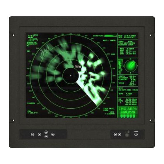
Naval Multi Display Models
JH 19T01 MIL - 19.0 inch Maritime Multi Display (MIL)
JH 20T03 MIL - 20.1 inch Maritime Multi Display (MIL)
JH 20T04 MIL - 20.1 inch Maritime Multi Display (MIL)
JH 23T02 MIL - 23.1 inch Maritime Multi Display (MIL)
Hatteland Display AS, Åmsosen, N-5578 Nedre Vats, Norway
Tel: (+47) 5276 3700 - Fax: (+47) 5276 5444 - e-mail: jhd-no@hatteland.com
User Manual MIL Series
Updated: 17 Jul 2007
For models:
-A1, -A2, -E1, -E2
Please visit our website for the latest electronic version of this manual.
Doc Id: INB100005-3 (Rev 9)

Advertisement

Table of Contents
loading

Summary of Contents for Hatteland JH 19T01 MIL

  • Page 1 Doc Id: INB100005-3 (Rev 9) For models: -A1, -A2, -E1, -E2 Please visit our website for the latest electronic version of this manual. Hatteland Display AS, Åmsosen, N-5578 Nedre Vats, Norway Tel: (+47) 5276 3700 - Fax: (+47) 5276 5444 - e-mail: jhd-no@hatteland.com...
  • Page 2 Information in this manual is copyrighted to the respective owners. All rights are reserved by Hatteland Display AS. This information may not, in whole or in part, be copied, photocopied, reproduced, translated or reduced to any electronic medium or machine-readable form without the prior written consent of Hatteland Display AS.
  • Page 3: Table Of Contents

    OSD Menu Functions ...............28 Physical Connections - MIL Models ..........33 Specifications ................. 5 Specifications - JH 19T01 MIL ............36 Specifications - JH 20T03 MIL ............37 Specifications - JH 20T04 MIL ............38 Specifications - JH 23T02 MIL ............39...
  • Page 4 Contents Technical Drawings ..............1 Technical Drawings - JH 19T01 MIL ..........42 Standard Version ................42 Technical Drawings - JH 20T03 MIL ..........43 Standard Version ................43 Technical Drawings - JH 20T04 MIL ..........44 Standard Version ................44 Technical Drawings - JH 23T02 MIL ..........45 Standard Version ................45...
  • Page 5 Contents Appendixes ................61 Serial Communication (SCOM) Interface ......... 62 Installation in display ..............62 Connectorization ................62 Address ..................62 Comm settings #1 (before Jan 2005 - pre-HW01 models) ...63 Comm settings #2 (after Jan 2005 - HW01 models) ....64 JH SCOM A1 & C1 Control Interface ...........65 Interface configuration ..............65 Brightness Control Operation ............65 Electrical Interface ................65...
  • Page 6 Contents Broadcast Command Response ..........73 MCC Response ................74 Inter-message Gap ...............74 Display Response and Addresses ..........74 Additional Commands ..............75 Video Controller Interface Commands .........76 Revision History - JHSCOM ............83 Pin Assignments - Common Connectors .......... 84 Basic Trouble-shooting ..............86 Declaration of Conformity ..............87 Return Of Goods Information ............
  • Page 7: Contents Of Package

    Contents of package This product is shipped with: Item Description Illustration 4 pcs of PAN M6X25 black bolts with M6 plastic washer. These should only be used to secure the display into a console. Note: If you prefer your own bolts, make sure they are minimum M6 and 25mm in length for security reasons.
  • Page 8 INB100005-3 (Rev 9)
  • Page 9: General

    General INB100005-3 (Rev 9)
  • Page 10: Introduction To Hatteland Display As

    IP66 rating. This new HATTELAND® Series 2 Panel Computers MMC2 and Displays MMD2 will be available from Q2 2006 onwards in 12in., 15in. and 19in. sizes. The concept allows easy scaling in sizes from small LCD screens up to large sizes of more than 32in LCD wide-screens.
  • Page 11: About This Manual

    The combination of the reliable design of the marine TFT-LCD modules, together with industrial computer boards, allows Hatteland Display to offer a product range for customer applications where space is critical and full function is desired in a single unit. In particular, the standardized ETX-board form factor allows full flexibility when it comes to processor choice. Because of...
  • Page 12: Basic Construction - Maritime Multi Display

    Basic Construction - Maritime Multi Display Basic Construction - Series 1 Touch Screen (option) Sun Visor (option) Mounting Bracket (option) Electronics / PCB’s Fans+Mechanics TFT Mount Frame Glass Centerbox Casing User Control Electronics Front Frame Rotary Bracket (option) Pot. Knob Frame Labels Hatch, optional w/logo Example with mounting bracket...
  • Page 13: Touchscreen Products

    Touchscreen products Introduction to products with touchscreen Both Resistive and Capacitive touchscreen solutions are used for our products. Please visit our website to find your exact type number and then determine if it uses Resistive or Capacitive. If you have a customized or tailored product, please check the specifications in this manual or third-party specifications from your supplier.
  • Page 14: Touchscreen Technology & Label Markings

    Please visit the 3rd party website as indicated on the label. You can also visit our website www.hatteland-display.com to view the full list of our models with touchscreen. Before using the touchscreen, t should be calibrated for your system. Please install the 3rd party software and use the Calibrate function from there.
  • Page 15: Product Labeling (Examples)

    Manufacturer : ELO TouchSystems Touch Controller : 2210 Serial Controller P/N 055165-000 Driver Download : www.elotouch.com VSD100564-2210 Product Information Manufacture: Product: Product type: Jakob Hatteland Display 19 Inch JH 19T01MMD-A1-1 NORWAY Serial Number 100W 115VAC/50-60Hz 20VAC/50-60Hz Product Description Manufacturer/Country Power Rating...
  • Page 16 INB100005-3 (Rev 9)
  • Page 17: Installation

    Installation INB100005-3 (Rev 9)
  • Page 18: Installation And Mounting Of Displays

    General Installation Recommendations Installation and mounting of displays 1. Most of our displays are intended for various methods of installation or mounting (panel mounting, bracket mounting, ceiling/wall mounting etc.); for details, please see the relevant mechanical drawings. 2. Adequate ventilation is a necessary prerequisite for the life of the display. The air inlet and outlet openings must definitely be kept clear;...
  • Page 19: Ergonomics

    General Installation Recommendations Ergonomics 1. Adjust the unit height so that the top of the screen is at or below eye level. Your eyes should look slightly downwards when viewing the middle of the screen. 2. Adjust screen inclination to remain gaze angle to the centre of the screen approximately perpendicular to the line of gaze.
  • Page 20: Cables

    General Installation Recommendations - The impairment of read-out from a display screen by direct light from lamps or the sun must be avoided. Rear windows must be blacked out by means of roller blinds or Venetian blinds. - Disturbing reflections on the screen of a display caused by pilot lamps and illuminated signs must be prevented by suitable measures (screening or relocating).
  • Page 21 General Installation Recommendations Maximum Cable Length The RGB/DVI cable should generally be kept as short as possible to provide a high quality output on the display. The maximum cable length will depend on the signal resolution and frequency, but also on the quality of the signal output from the computer. Recommended is 60Hz vertical frequency.
  • Page 22 INB100005-3 (Rev 9)
  • Page 23: Operation

    Operation MIL Products INB100005-3 (Rev 9)
  • Page 24: User Controls

    User Controls START-UP: The unit features a Instant-ON / Delay-OFF functionality, which ensures that it is not turned off by user accident. The location is on the right bottom side of the unit together with the other user controls as illustrated in the labels below. There exists several types / sizes of labels which reflects some of our standard functionalities like for instance buzzer.
  • Page 25 Operation FIG 1 MENU Access Button UP/Down Buttons Adjust Buttons -/+ USER CONTROLS: The On Screen Display (OSD menu) controls are located under the metal hatch on the left side of the unit. To loosen it, use a suitable screwdriver and dismount the two screws as illustrated in FIG 1. To begin understanding the workflow of the menu, follow these steps for a quick start.
  • Page 26: Osd Menu Overview

    OSD Menu Overview Mode 1 - Function layout in RGB / DVI MODE Simplified/Normal OSD Menu: (User menu) Note that to be in RGB / DVI MODE, a computer signal must be present in full screen, i.e Windows or other operating system/radar system. Having a PIP view simultaneously will not interfere or change the menu structure in any way.
  • Page 27 OSD Menu Overview Mode  - Function layout in VIDEO MODE Simplified/Normal OSD Menu: (User menu) Note that to be in VIDEO MODE, a video signal must be present in full screen, i.e from a camera, VCR or DVD player. Video Adjustment Color Tint...
  • Page 28: Osd Menu Functions

    OSD Menu Functions BRIGHTNESS AND CONTRAST: (No function in DVI mode) Selecting this function will enable the user to adjust brightness and contrast for the display. (No Function in DVI) BRIGHTNESS: Increase/decrease brightness level, total: 100 steps (No Function in DVI) CONTRAST: Increase/decrease contrast level, total: 100 steps COLOR TEMPERATURE Selecting this function will enable the user to modify the warmness of the picture.
  • Page 29 OSD Menu Functions STATUS: Selecting this function will display graphic information such as resolution and frequency. POSITION: (No function in DVI mode) Selecting this function will enable the user to position the image within the display area. (No Function in DVI) IMAGE UP/DOWN : Position the image vertically using “UP”...
  • Page 30 OSD Menu Functions GRAPHIC SCALING MODES: Selecting this function will enable the user to configure the graphic scaling of the RGB/DVI or VIDEO image. The change will happen realtime. Note: Some of these functions will impact on image quality, and will therefore not show the optimal 1:1 picture with correct aspect ratio and resolution suitable for the TFT module.
  • Page 31 OSD Menu Functions UTILITIES: Selecting this function will enable the user to configure the OSD menu, define hot keys, verify BIOS Firmware version and miscellaneous operations. USER SETTING: (Press “+” to access the sub-menu) DPMS : Disable / Enable the DPMS function. DISPLAY INPUT : Disable / Enable input source name upon power up.
  • Page 32 OSD Menu Functions CALIBRATE RGB GAIN : Color Calibration. Press “+” to automatically adjust it. DISPLAY ORIENTATION: (Press “+” to access the sub-menu) Will flip/inverse the display area including PIP view. Press “+” to choose between: Normal / Horizontal Inverse / Vertical Inverse / Inverse LOAD (FACTORY) DEFAULTS: (Press “+”...
  • Page 33: Physical Connections - Mil Models

    Physical Connections - MIL Models Connection area of display (illustration) Touchscreen (opt) Remote Control(opt) Power Input RGB IN Composite Video In (5 x BNC) (1 x BNC) NOTE: There is no Composite Video In on JH 20T03 MIL model. TOUCHSCREEN: (optional) Connect the RS-232 cable to the D-SUB 9P Connector (female) on the rear side of the TFT display.
  • Page 34 Physical Connections - MIL Models POWER INPUT: (DC Version) Secure the cables (check polarity!) to the screw terminal, you may secure the cable further by mounting it to the base mounted cable tie clamp. The internal DC power module supports voltage from 12 to 24 VDC depending on the product model.
  • Page 35: Specifications

    Specifications INB100005-3 (Rev 9)
  • Page 36: Specifications - Jh 19T01 Mil

    : 1 x BNC Connector • Pixel pitch (RGB) : 0.294 (H) x 0.294 (V) mm • AC Power signal : Std IEC Inlet - Model JH 19T01 MIL A1 • Response Time : 15 ms (typical), “black” to “white” • DC Power signal : Screw Terminal - Model JH 19T01 MIL A2 •...
  • Page 37: Specifications - Jh 20T03 Mil

    Specifications - JH 20T03 MIL PRODUCT SPECIFICATIONS - JH 20T03 MIL Note: All specifications are subject to change without prior notice! TECHNICAL DESCRIPTION: MECHANICAL DESCRIPTION: TFT Technology: Physical Dimensions: • 20.1” viewable image size • 534 (W) x 485 (H) 79.50 (D) •...
  • Page 38: Specifications - Jh 20T04 Mil

    Specifications - JH 20T04 MIL PRODUCT SPECIFICATIONS - JH 20T04 MIL Note: All specifications are subject to change without prior notice! TECHNICAL DESCRIPTION: MECHANICAL DESCRIPTION: TFT Technology: Physical Dimensions: • 20.1” viewable image size • 534 (W) x 481 (H) 73 (D) •...
  • Page 39: Specifications - Jh 23T02 Mil

    Specifications - JH 23T02 MIL PRODUCT SPECIFICATIONS - JH 23T02 MIL Note: All specifications are subject to change without prior notice! TECHNICAL DESCRIPTION: MECHANICAL DESCRIPTION: TFT Technology: Physical Dimensions: • 23.1 inch viewable image size • 584 (W) x 534 (H) 72 (D) •...
  • Page 40 INB100005-3 (Rev 9)
  • Page 41: Technical Drawings

    Technical Drawings INB100005-3 (Rev 9)
  • Page 42: Technical Drawings - Jh 19T01 Mil

    Technical Drawings - JH 19T01 MIL Standard Version INB100005-3 (Rev 9) IND100132-39...
  • Page 43: Technical Drawings - Jh 20T03 Mil

    Technical Drawings - JH 20T03 MIL Standard Version INB100005-3 (Rev 9) IND100132-40...
  • Page 44: Technical Drawings - Jh 20T04 Mil

    Technical Drawings - JH 20T04 MIL Standard Version INB100005-3 (Rev 9) IND100132-41...
  • Page 45: Technical Drawings - Jh 23T02 Mil

    Technical Drawings - JH 23T02 MIL Standard Version INB100005-3 (Rev 9) IND100132-42...
  • Page 46 INB100005-3 (Rev 9)
  • Page 47: Technical Drawings - Accessories

    Technical Drawings - Accessories INB100005-3 (Rev 9)
  • Page 48: 17" > 23" Rotary Bracket

    Technical Drawings - Accessories 17” > 23” Rotary Bracket INB100005-3 (Rev 9) IND100132-46...
  • Page 49: 17" > 20" Bracket

    Technical Drawings - Accessories 17” > 20” Bracket INB100005-3 (Rev 9) IND100132-69...
  • Page 50: 19" Tft To 21" Crt Adapter

    Technical Drawings - Accessories 19” TFT to 21” CRT adapter INB100005-3 (Rev 9) IND100132-44...
  • Page 51: 19" Sun Visor

    Technical Drawings - Accessories 19” Sun Visor INB100005-3 (Rev 9) IND100132-67...
  • Page 52: 20" Sun Visor

    Technical Drawings - Accessories 20” Sun Visor INB100005-3 (Rev 9) IND100132-111...
  • Page 53: 23" Sun Visor

    Technical Drawings - Accessories 23” Sun Visor INB100005-3 (Rev 9) IND100132-112...
  • Page 54: Vesa Bracket - 19

    Technical Drawings - Accessories VESA Bracket - 19” INB100005-3 (Rev 9) IND100132-45...
  • Page 55: Vesa Bracket - 20

    Technical Drawings - Accessories VESA Bracket - 20” INB100005-3 (Rev 9) IND100132-115...
  • Page 56: Vesa Bracket - 23

    Technical Drawings - Accessories VESA Bracket - 23” INB100005-3 (Rev 9) IND100132-116...
  • Page 57: Water Cover - 19

    Technical Drawings - Accessories Water Cover - 19” INB100005-3 (Rev 9) IND100132-80...
  • Page 58: Water Cover - 20

    Technical Drawings - Accessories Water Cover - 20” INB100005-3 (Rev 9) IND100132-119...
  • Page 59: Water Cover - 23

    Technical Drawings - Accessories Water Cover - 23” INB100005-3 (Rev 9) IND100132-120...
  • Page 60 INB100005-3 (Rev 9)
  • Page 61: Appendixes

    Appendixes INB100005-3 (Rev 9)
  • Page 62: Serial Communication (Scom) Interface

    Serial Communication (SCOM) Interface Installation in display Connectorization The remote control has either two or one 9 pin D-subs for communication. For systems with more than one unit, the units are connected together through the unoccupied D-sub. It is regardless which one is used, but normally COM-1 is connected to another unit, and COM-2 is connected to the PC.
  • Page 63: Comm Settings #1 (Before Jan 2005 - Pre-Hw01 Models)

    Serial Communication (SCOM) Interface Comm settings #1 (before Jan 2005 - pre-HW01 models) The communication options are set by switches, placed at the backside of the display. For most displays, these switches are labelled like seen on the illustration below. For adjustments, a thin object is required for reaching the switches. Some displays do not have this label or the dedicated holes.
  • Page 64: Comm Settings #2 (After Jan 2005 - Hw01 Models)

    Serial Communication (SCOM) Interface Comm settings #2 (after Jan 2005 - HW01 models) The communication options are set by switches, placed at the backside of the display. These switches are protected behind a hatch mounted with four screws. Unscrew those, and remove the hatch. The communication settings are placed like seen on the illustration below. For adjustments, a thin object is required for reaching the switches.
  • Page 65: Jh Scom A1 & C1 Control Interface

    Serial Communication (SCOM) Interface JH SCOM A1 & C1 Control Interface This document defines the electrical signals, connectorization, serial data format, and communication protocol of the A1 and C1 version Serial Communication Control Interface. Difference between A1 and C1 is that C1 version provides filtered Dsub contacts for military applications.
  • Page 66: Block Diagram

    Block Diagram Communication Interface INB100005-3 (Rev 9) IND100084-1...
  • Page 67: Connectorization At Display

    Serial Communication (SCOM) Interface Connectorization at Display The display provides two or one 9 pin D-shell with socket contacts (depending on model). Pin assignments at the display are as shown below. RS 22 RS22/ RS 5 full duplex RS 5 half duplex RxD- TxD+ Data +...
  • Page 68: Data Rate

    Serial Communication (SCOM) Interface Data Rate The display is configured to transmit and receive data at 9600 bits/second. Data Format Data shall be transmitted with no parity, 8 data bits, one start bit, and one stop bit. Message Format The basic message format shall be as follows: Byte # 2,, 7, etc...
  • Page 69: Data Length (Len)

    Serial Communication (SCOM) Interface CMD 0 CMD 1 CMD 2 ASCII Description 0x42 0x52 0x54 “BRT” Brightness Command 0x4D 0x41 0x4E “MAN” Manufacturer ID Code 0x56 0x45 0x52 “VER” Display ID Version Number 0x50 0x4F 0x54 “POT” Potentiometer control 0x4D 0x43 0x43 “MCC”...
  • Page 70: Manufacturer Id "Man

    Serial Communication (SCOM) Interface A setting of 0xFF will indicate maximum brightness. Intermediate values will control brightness over the range from minimum to maximum luminance. If the data checksum is valid and the brightness was set, the display will reply to this command with an ACK attention code.
  • Page 71: Potentiometer Control "Pot

    Serial Communication (SCOM) Interface 0x07 0xFF 0x56 0x45 0x52 0x00 0x0C Display Version 1.0: 0x06 0x05 0x56 0x45 0x52 0x03 0x04 0x01 0x01 0x00 0xFD Potentiometer control “POT” The LCD Display may allow the backlight to be controlled by the local control (potentiometer) mounted on the front of the display, by the remote control, or by the combination of the two.
  • Page 72: Display Type/Model Number "Typ

    Serial Communication (SCOM) Interface Acknowledge 50% Contrast: 0x06 0x03 0x4D 0x43 0x43 0x06 0x1D 0x82 0x41 0x38 0x30 0x38 0x30 0x6C Display Type/Model Number “TYP” This command shall be sent to the display in order to identify the display type by its model number / part number. No data shall be sent with this command. The display will reply to this command with an ACK attention code.
  • Page 73: Individually Addressed Command Response

    Serial Communication (SCOM) Interface Individually Addressed Command Response The display will output the required response within Tr = 2.5 character periods after the last byte of a command message is received (2.6mS at 9600 bit/sec), except as specified herein. Elapsed Time Counter “ETC” [ Note: This command is not available on pre Feb 2005 units ] The monitor features an elapsed time counter which counts the total number of hours that the display has been switched on.
  • Page 74: Mcc Response

    Serial Communication (SCOM) Interface + 1. The maximum Lr for each command are shown in the table below: Command Example: For the BRT command, and 8 displays, this corresponds to Te = (2.5 * 10 + 9 * 10) * 8 / 9600 = 95.8 ms MCC Response For broadcast messages in RS485 mode, the data field of an ACK is limited to 9 bytes, and LEN of command + LEN of ACK is limited to 14.
  • Page 75: Additional Commands

    Serial Communication (SCOM) Interface the display shall ignore the message. A NAK message shall not be generated. If the data checksum is valid, but the value in the DATA field associated with a command is invalid (out of range, undefined, etc.), the Display shall generate a NAK message indicating the current data value in the DATA field.
  • Page 76: Video Controller Interface Commands

    Video Controller Interface Commands (Note: Some commands may not be available on older models). Revision 0.09.00 COMMAND TABLE Commands to implement switch mount control buttons Function Command Description Acknowledge (if enabled) Brightness control 0x81, Set brightness = Brightness. nn | “+” | “-” | value/increment/decrement “r”...
  • Page 77 Video Controller Interface Commands PIP window size 0xa6, Select PIP window size = Main selected. select nn | PIP window size value PIP off if “nn” = “00”. “r” | “R” | Reset “?” Query PIP source select 0xa7, Select input main = Main selected.
  • Page 78 Video Controller Interface Commands Rotate video image 0xc7, “0” | “1” Disable/enable video rotate “0” – normal video image. “1” – rotated video image. Scaling Mode 0x8c, Set graphic image scaling mode Image expansion on/off. “0” | “1” | “2” | “3” “0”...
  • Page 79 Video Controller Interface Commands Scalar V stretch 0xb0, Set vertical stretch factor for Scalar vertical stretch. non-linear scale mode = nnn | “+” | “-” | value/increment/decrement “r” | “R” | Reset “?” Query Select OSD 0x95, Select language = “0”...
  • Page 80 Video Controller Interface Commands OSD H position 0x90, Set osd_hpos = OSD horizontal position. nnn | “+” | “-” | value/increment/decrement “r” | “R” | Reset “?” Query OSD V position 0x91, Set osd_vpos = OSD vertical position. nnn | “+” | “-” | value/increment/decrement “r”...
  • Page 81 Video Controller Interface Commands Auto-calibration 0xc5 Start auto-calibration of gain of “0” – fail. the RGB amplifier. “1” – successful. Set gamma data for 0xbf, mm, c, “?” Query gamma data for color c “nn” = gamma data user defined gamma index mm ( c = 0 for color Red, curve c=1 for color Green,...
  • Page 82 Video Controller Interface Commands Other Control Function Command Description Acknowledge (if enabled) Select video mode 0xc2, nn Current vmode = nn. Current video mode selected. Auto-setup 0xc3 Start auto-setup of current “0” – fail. vmode. “1” – successful. Command 0xc4, nn Check whether a command is “0”...
  • Page 83: Revision History - Jhscom

    Revision History - JHSCOM Rev. Date Notes 26 nov 01 Preliminary release. 06mar02 1’st Release Remote control interface specification 06mar02 Changed Pin description for Half duplex RS-485. Renamed document description to Specification of Serial Communication 17oct02 Control Interface. Corrected Pin assignment of RS-232 (Tx and Rx). Added new MCC commands.
  • Page 84: Pin Assignments - Common Connectors

    Pin Assignments - Common Connectors Note: Not all connectors may be available on your specific product. This depends on the amount of additional hardware installed from factory, or customized solutions. These pin assignments are for the common connectors used. Connectors are seen from users Point Of View (POV). Pin Assignments - USB TYPE A Pin Assignments - RJ5 10/100 LAN Pin 2: Negative Data...
  • Page 85 Pin Assignments - Common Connectors Pin Assignments - 25P Parallel 1 12 11 10 9  7 6 5   2 1 25 2 2 22 21 20 19 1 17 16 15 1 Pin 01 - STROBE This signal indicates to the printer that data at PD7..0 are valid. Pin 02 - DATA0 Parallel data bus from PC board to printer.
  • Page 86: Basic Trouble-Shooting

    Basic Trouble-shooting COMMON ERRORS: (This is a generic description of possible issues for a varity of products) If for some reason there should be something wrong with the picture quality or no picture present, check the symptoms carefully and try to cure it with the hints below: NO PICTURE / LED BEHAVIOUR: If there is no light at all in the LED at the FRONT, check power cables.
  • Page 87: Declaration Of Conformity

    Declaration of Conformity We, manufacturer Hatteland Display AS Åmsosen, N-5578 Nedre Vats, Norway declare under our sole responsibility that the JH MMD, JH MMC, JH STD, JH MIL, HT STD (Series 1) and HD MMD, HT MMC (Series 2) products is in conformity with the following standards in accordance with the EMC Directive.
  • Page 88: Return Of Goods Information

    Return of goods: (Applies not to warranty/normal service/repair of products) Hatteland Display referenced as “manufacturer” in this document. Before returning goods, please contact your system supplier before sending anything directly to manufacturer. When you return products after loan, test, evaulation or products subject for credit, you must ensure that all accessories received from our warehouse is returned.
  • Page 89: Terms

    Jakob Hatteland Display AS charge NOK 50,- in forwarding fee for orders below NOK 1000,-. For orders below NOK 1000,- Jakob Hatteland Supply AS charge freight according to expenses, and NOK 25,- for packing. For handling requested beyond ordinary hours NOK 250,- is charged. Express service is charged with NOK 100,- + freight charges. All the companies charge freight according to expenses for orders above NOK 1000,-.
  • Page 90 Terms 12) CANCELLATION / RETURN Binding sales contract is concluded when we have confirmed customer’s purchase order. Any disagreements in our order confirmation must be reported to seller within 6 days. The agreement can not be altered without our permission, after acceptance from our supplier.
  • Page 91: Notes

    For certain versions the entire graphical board must be changed by a qualified Hatteland technician or a representative. A BIOS software upgrade is not possible.
  • Page 92 Notes Appendix INB100005-3 (Rev 9) IND100077-24...
  • Page 93: Revision History

    Revision History Rev. Date Notes 12 Feb 04 First release, User Manual. Pressed & internet version. 18 Mar 04 Updated EMI test specifications and datasheets. 28 Apr 04 Added Declaration Of Confirmity Added Book ID on all pages, and minor maintenance. 12 Nov 04 Updated JH 20T04 MIL drawing 24 Jan 05...
  • Page 94 General - Appendix INB100005-3 (Rev 9) IND100077-12...
  • Page 95 General - Appendix INB100005-3 (Rev 9) IND100077-12...
  • Page 96: Contact Information

    Contact Information Head office, Vats / Norway: Hatteland Display AS Åmsosen N-5578 Nedre Vats, Norway Tel: +47 5276 3700 Fax: +47 5276 5444 Sales office, Oslo / Norway: Hatteland Display AS Gjerdrums vei 12 N-0484 Oslo, Norway Tel: +47 5276 3700 Fax: +47 2258 6790 Sales office, Tønsberg / Norway:...

This manual is also suitable for:

Jh 20t03 milJh 20t04 milJh 23t02 mil

Table of Contents