Table of Contents
Advertisement
Quick Links
Owner's Guide
and
Installation Instructions
MVB
Modulating Vertical Burner
Water Heater
Models 910500 • 910750 • 911000 • 911250
• 911500 • 911750 • 912000
This water heater must be installed and serviced by an authorised person.
This water heater must be certified in accordance with AS 3814 before being brought into service
Please leave this guide with a responsible officer.
Raypak Inc Use only: Effective: 4-01-21
Replaces: 241727 Rev 1
P/N 241727 Rev 2
1
Advertisement
Table of Contents

Related Manuals for Raypak 910500


Summary of Contents for Raypak 910500
- Page 1 Installation Instructions Modulating Vertical Burner Water Heater Models 910500 • 910750 • 911000 • 911250 • 911500 • 911750 • 912000 This water heater must be installed and serviced by an authorised person. This water heater must be certified in accordance with AS 3814 before being brought into service Please leave this guide with a responsible officer.
- Page 2 PATENTS This water heater may be protected by one or more patents or registered designs in the name of Raypak Inc. TRADEMARKS ® Registered trademark of Rheem Australia Pty Ltd. Trademark of Rheem Australia Pty Ltd.
-
Page 3: Table Of Contents
CONTENTS HOUSEHOLDER OR RESPONSIBLE OFFICER – This booklet contains important information about your new water heater, including terms of the Rheem warranty. The other pages are intended for the installer but may be of interest We recommend you read pages 4 to 10. WARRANTY ......................................... -
Page 4: Warranty
RAYPAK WATER HEATER WARRANTY – AUSTRALIA ONLY RAYPAK MVB WATER HEATER MODELS 910500, 910750, 911000, 911250, 911500, 911750, 912000 1. THE RHEEM WARRANTY – GENERAL This warranty is given by Rheem Australia Pty Limited ABN 21 098 823 511 of 1 Alan Street, Rydalmere New South Wales. - Page 5 g) Failure to maintain the water heater in accordance with the Owner's Guide and Installation Instructions. h) Transport damage. Fair wear and tear from adverse conditions (for example, corrosion). Cosmetic defects. Rheem may reject a claim under this warranty in its sole discretion if a third party solar diverter is connected to the water heater.
-
Page 6: Safety,Warnings, Installation Notes
• Improper installation, adjustment, alteration, service or maintenance can cause injury or property damage. For ® assistance or additional information consult your Raypak distributor, qualified installer, or Rheem Service agent. • DO NOT store flammable or combustible materials near the water heater. - Page 7 • DO NOT use Propane / Butane gas mixtures in a Propane model. A Propane model is designed to operate on Propane only. The use of Propane / Butane mixture, such as automotive LPG fuel, in a Propane model is unsafe and can cause damage to the water heater. •...
- Page 8 • Close the isolation valves on the cold and hot water branches to shut down an individual water heater in a bank. TO TURN ON THE WATER HEATER WARNING: If you smell gas do not attempt to turn on the water heater. •...
- Page 9 • in compliance with the Plumbing Standard AS/NZS 3500.4, ▪ The water heater is suitable for either indoor or outdoor installation. • in compliance with the Australian / New Zealand Wiring Rules AS/NZS 3000, ▪ Isolation switches must be installed in the electrical circuit to the water heater in accordance with the Wiring Rules, so the water heater can be switched off.
-
Page 10: About Your Water Heater
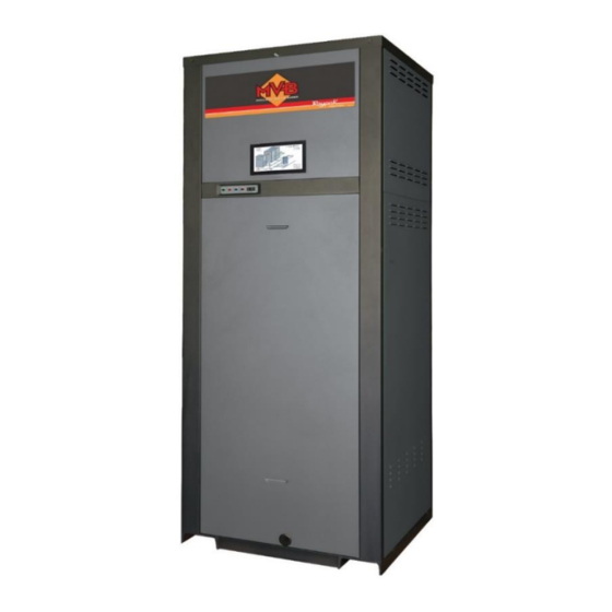
This water heater is designed for the purpose of heating potable water or hydronic heating applications. Its use in an application other than this may shorten its life. MODEL TYPE Congratulations for choosing a Raypak MVB water heater. ® The operation of the water heater depends on the application. For hot water applications up to 71 C, a W model will be installed. - Page 11 HOW HOT SHOULD THE WATER BE? The water heater features an adjustable electronic thermostat, which allows the most Maximum user suitable temperature for the application to be adjustable temperature chosen. for W models To meet the requirements of the National Plumbing Standard the temperature of the stored water for hot water applications must not be below 60°C.
-
Page 12: How Your Water Heater Works
PRECAUTIONS Where damage to property can occur in the event of the water heater leaking, the water heater should be installed in a safe tray or suitably bunded. Construction, installation and draining of a safe tray or bunding should comply with AS/NZS 3500.4 and all local codes and regulatory authority requirements. The water heater must be maintained in accordance with the Owner’s Guide and Installation Instructions. -
Page 13: Save A Service Call
Warning: Hotter water increases the risk of scald injury. • Water heater size Do you have the correct size water heater for your requirements? The sizing guide in the Raypak sales literature and on the Rheem website (www.rheem.com.au) suggests average sizes. - Page 14 Heater Errors When an error condition occurs, the controller will display an error code on the user interface. These error codes and several suggested corrective actions are included in the MVB Fault Text section on page 14. Heater Faults When a fault condition occurs, the controller will flash a red light on the PIM™ and display the error code in the Toolbox menu on the user interface.
- Page 15 Error Item Description and Troubleshooting OUTLET SEN Check the outlet water sensor and its wiring. LIMIT SEN Check the high limit sensor and its wiring. INLET SEN Check the inlet sensor and its wiring. Check PIM™ wiring. GAS PRESS IGNITION Reset control, push and release RESET button LIMIT TRIP Water heater temperature tripped the high limit.
- Page 16 Sensor Resistance Values Water Sensor/ Outdoor Sensor Water Resistance Temperature (ohms) (°C) 32550 25340 19870 15700 12490 10000 8059 6535 5330 4372 3605 2989 2490 2084 1753 1481 1256 1070 Table 4: 10K/25 NTC (Curve J) Sensor Resistance Values IF YOU HAVE CHECKED ALL THE FOREGOING AND STILL BELIEVE YOU NEED ASSISTANCE, PHONE YOUR NEAREST RHEEM SERVICE DEPARTMENT.
-
Page 17: Maintenance Requirements
MAINTENANCE REQUIREMENTS SERVICING Warning: Servicing of a gas water heater must only be carried out by authorised personnel. For peak performance it is suggested that the water heater be serviced by your nearest Rheem Service Department prior to the winter period where light to medium hot water usage occurs, and six monthly where medium to heavy usage occurs. -
Page 18: Water Supplies
Rheem warranty to apply to, the pressure relief valve on the Raypak water heater and the temperature pressure relief valve and cylinder of the storage tank connected to the system. Refer to the... - Page 19 CHANGE OF WATER SUPPLY The changing or alternating from one water supply to another can have a detrimental effect on the operation and / or life expectation of the water heater, the storage cylinder and the relief valves. Where there is a changeover from one water supply to another, e.g. a rainwater tank supply, bore water supply, desalinated water supply, public reticulated water supply or water brought in from another supply, then water chemistry information should be sought from the supplier or it should be tested to ensure the water supply meets the requirements given in these guidelines for the Rheem warranty to...
-
Page 20: Installation
INSTALLATION INSTALLATION STANDARDS The water heater must be installed: • by a qualified person, and • in accordance with the installation instructions, and • in compliance with Standards AS/NZS 3500.4, AS/NZS 5601.1 AS/NZS 3000 and AS 3814 as applicable under local regulations, and all local codes and regulatory authority requirements. •... - Page 21 WATER HEATER APPLICATION THIS WATER HEATER IS NOT SUITABLE FOR POOL HEATING. This water heater is designed for the purpose of heating potable water or for hydronic heating applications. Its use in an application other than this may shorten its life. If this water heater is to be used where an uninterrupted hot water supply is necessary for the application or business, then there should be redundancy within the hot water system design.
- Page 22 You must be able to read the information on the rating label located at the back of the water heater. The water heater must not be installed in an area with a corrosive atmosphere where chemicals are stored or where aerosol propellants are released. Remember the air may be safe to breathe, but when it goes through a flame, chemical changes take place which may attack the water heater.
- Page 23 The water heater must be installed with service access in mind. There are also special requirements in AS/NZS 5601.1 for water heaters installed in a garage, an enclosed space and other locations. Remember all local authorities have regulations about putting water heaters into roof spaces. Minimum Clearance from Minimum Service Heater Side...
- Page 24 Table 6: MVB Dimensions and Technical Data MVB Model 910500 910750 911000 911250 911500 911750 912000 Natural & Propane Input MJ/h 1054 1319 1582 1846 1990 Output Dimensions 1092 1245 1397 1549 1702 1905 2057 1118 1270 1422 1575 1727...
- Page 25 Fig 3 – Multiple MVB with Vertical Room Sealed Flueing Showing Typical Gas, Water, Air Intake and Flue Configurations...
-
Page 26: Connections - Plumbing
CONNECTIONS – PLUMBING COLD WATER SUPPLY / MAKEUP All plumbing work must be carried out by a qualified person and in accordance with the National Plumbing Standard AS/NZS 3500.4 and local authority requirements. Water Heating Applications (W Models) An isolation valve and non-return valve must be installed on the cold water line to the system. - Page 27 Operation Type W Models H Models Relief Valve Setting (kPa) 1000 (850) Expansion Control Valve (ECV) Setting (kPa) 850 (700) Minimum Supply Pressure System water temperatures up to 65 C (kPa) 70 (7m) 70 (7m) System water temperatures above 65 C (kPa) 120 (12m) 120 (12m)
- Page 28 Failure to do this may cause blockages and/or damage to the water heater which is not covered by warranty. IF THERE IS ANY DOUBT ABOUT THE SYSTEM, DRAIN AND FLUSH AS A PRECAUTION. Water Connection Sizes MVB Model 910500 910750 911000 911250 911500...
- Page 29 3 Units 4 Units Pump Size pipe pipe pipe pipe Model Model speed speed speed speed 910500 UPS32-80N 910750 UPS32-80N 911000 Magna 1 40-120 911250 Magna 1 40-120 911500 Magna 1 40-120 911750 Magna 1 65-150 912000 Magna 1 65-150 Note: Manifold header sizes are minimum requirements for water heater performance.
- Page 30 4 Units Pump Size pipe pipe pipe pipe Model Model speed speed speed speed 910500 UPS32-80 910750 Magna 1 40-120 911000 Magna 1 40-120 911250 Magna 1 40-120 911500 Magna 1 65-150 911750 Magna 1 65-150 912000 Magna 1 65-150 Note: Manifold header sizes are minimum requirements for water heater performance.
- Page 31 Intermittent Pump Operation The MVB can control up to three pumps simultaneously depending on water heater type and system configuration. The pumps will be energised and de-energised based on system parameters including pump run-on at the end of a heating cycle. Refer to “Applications and Modes” on page 52. These include: W Models 1.
- Page 32 Magna1 pumps have nine settings which are as follows (shown in order of button progression from factory PP2 setting): CCIII CCII Grundfos Eye Indication Power OFF pump not running Power ON pump running in direction of rotating LEDs Alarm. The pump has stopped SYSTEM INSTALLATION Where the water heater is supplied as part of a package, including the storage cylinder and pump, the installation must comply with the requirements supplied in this manual and/or the drawing provided.
- Page 33 Equa-Flow Principles ® The principle of Equa-Flow is to ensure the demand on each water heater, or storage cylinder in the ® bank is the same as any other. To achieve this, the following is necessary: 1. The cold water manifold (cold header assembly) must be designed to balance the flow to each storage tank i.e.
- Page 34 3. The hot water manifold (hot header assembly) must be designed to balance the flow from each storage tank i.e. each branch line must be the same diameter and length and be fitted with identical ball or gate valves (refer to diagram below). Fig 7: Storage Tank Hot Water Manifold Arrangement...
- Page 35 Plumbing Diagrams Fig 8: Typical Installation – One Water Heater, One Storage Tank Fig 9: Typical Installation Multiple Water Heaters, Multiple Storage Tanks...
- Page 36 Mechanical, Hydronic and Process Heating Applications Piping NOTE: Hot water heating systems all have unique levels of operating diversity that must be accounted for in the system design. The system should always include adequate system flow in excess of the connected water heater flow for proper operation.
- Page 37 “X” – MAXIMUM 4 x SYSTEM PIPE DIAMETERS OR 300mm WHICHEVER IS SMALLER Fig 11: Typical Installation – Mechanical Heating Primary Flow and Return Closed Loop Water Source Heat Pump Applications • The bypass pipe diameter MUST be the same as the inlet and outlet pipes. •...
-
Page 38: Connections - Gas
Gas piping MUST have a sediment trap ahead of the heater gas controls, refer to Fig 13 on page 38. An isolation valve and disconnection union must be installed to allow servicing and removal of the water heater. Refer to AS/NZS 5601.1 for the correct pipe sizing. GAS CONNECTIONS MVB Model 910500 910750 911000 911250 911500... - Page 39 The gas valve pressure regulator on the heater is nominally preset as noted in Table 15 on page 39. Manifold Gas Pressure Setting High Fire Values (kPa) MVB Model Nat. Gas Propane 910500 -1.17 -1.32 910750 -1.15 -1.44 911000 -1.15...
-
Page 40: Connections - Flue
FLUEING The MVB is supported by a range of stainless steel flue components suitable for positive pressure condensing operation. Dia 150mm suits 910500, 910750 and 911000. Dia 2000mm suits 911250, 911500, 911750 and 912000. The following parts are available: Flue Adaptor & Clamp Kit... - Page 41 Lock Band Clamp (1 per flue piece) Lock Band Screw Mounting Band (1 per 1.5m of run) Dia 150 - AQ94200114 Dia 150 - AQ94200115 Dia 150 - AQ94200116 Dia 200 - AQ94200135 Dia 200 - AQ94200136 Dia 200 - AQ94200137 Horizontal Terminal (can be cut to length) Dia 150 - AQ94200121 Dia 200 - AQ94200144...
- Page 42 FLUE TERMINAL LOCATION In addition to the requirements of AS/NZS 5601.1, the following should be observed: NOTE: During winter months check the flue terminal and make sure no blockage occurs from build-up of snow or ice. 1. Condensate can freeze on the flue terminal. Frozen condensate on the flue terminal can result in a blocked flue condition.
- Page 43 A condensate trap MUST be fitted at the flue outlet of the water heater, regardless of the flue termination type. The condensate drain must be primed with water to prevent gas flue leak and must be routed to drain in accordance with local codes and regulations. WARNING: The MVB operates with a positive pressure flue.
- Page 44 6. Fit the outdoor mounting bracket behind the flue and secure to the ground. Refer to the instructions supplied with the bracket for details. 7. The base of the flue terminal must be at least 250mm above the top of the MVB and 900mm above the air intake to the MVB.
- Page 45 7. The Rheem supplied horizontal flue terminal MUST be used. Fit the horizontal flue terminal on the other side of the wall and secure to the flue pipe with the supplied screw clamp. The flue terminal can be cut to length as required and debur. 8.
- Page 46 INDOOR INSTALLATION The water heater must be installed with service access in mind. This heater must be supplied with sufficient quantities of non-contaminated air to support proper combustion and equipment ventilation. Combustion air can be supplied via conventional means where air is drawn from the area immediately surrounding the water heater (room sourced), or via direct vent, where combustion air is drawn directly from outside (room sealed).
- Page 47 Max Air Inlet Length** (m) Flue Max. Flue Flue Air Intake Size Length** Ø 150 Ø 200 Ø 250 Model Material Pipe (mm) Material Stainless 910500 316L Steel, Stainless Galvanized 910750 Steel Steel, PVC, minimum 911000 ABS, CPVC 911250 Stainless 316L Steel, 911500...
- Page 48 VERTICAL TERMINATING FLUES Refer to Table 17 on page 47 for the maximum length of flue run. Lubricant is available to lubricate the flue gaskets for ease of installation. DO NOT use soapy water. 1. The connection from the water heater to the vertical stack must be as direct as possible and shall be the same diameter as the water heater flue outlet.
- Page 49 HORIZONTAL TERMINATING FLUES These installations utilise the heater-mounted blower to vent the combustion products to the outdoors. Combustion air is taken from inside the room and the flue terminal is installed horizontally through the wall to the outdoors. Adequate combustion and ventilation air must be supplied to the equipment room in accordance with AS/NZS 5601.1.
- Page 50 CAUTION: Combustion air must not be contaminated by corrosive chemical fumes which can damage the heater and void the warranty. (Refer to “Inside Air Contamination” on page 46.) Water heaters located indoors must be installed in a protective enclosure or properly constructed plant room.
- Page 51 Fig 20: Horizontal Room Sealed Flueing Fig 21: Vertical Room Sealed Flueing MOTORIZED COMBUSTION AIR DAMPERS OR LOUVERS When dampers or louvers are communicating directly with outside combustion air, they must be interlocked with each appliance in the equipment room, to ensure proper operation. See “Extra Low Voltage and Ancillary Connections”...
-
Page 52: Applications & Modes
APPLICATIONS AND MODES The VERSA IC Control system employed in the MVB is designed for a wide range of applications. The installer/design engineer should refer to the following Modes to determine which best fits the intended application and functionality for the unit being installed. Type H models have three modes available. Type W models will only have the W configuration available to them for use with potable water applications when directly connected to a hot water storage tank. - Page 53 Fig. 23: W Models - Master/Slave with Tank Operational Notes • Heater A VERSA control board DIP switch 2 must be set to ON (Master). Heaters B, C and D VERSA control board DIP switch 2 must be set to OFF (slave). Refer to Cascade System Connections on page 77.
- Page 54 This mode selection is for domestic hot water systems with single or multiple water heaters (Maximum 4 water heaters) with set point temperature between 72 C and 82 The system temperature is controlled by an aquastat (Pump C Controller) located in the bottom of the storage tank.
- Page 55 Fig 25: MODE 1 – Master/Slave with DHW >71 Operational Settings • Operation Mode parameter in ADJUST menu must be set to 3 (refer to H Model High Temp DHW C Max) - ADJUST Menu Settings on page 55 for parameter settings and Adjust Menu on page 88).
- Page 56 Only available to be viewed/changed if PIM DIP switch 1 is ON Manual Diff 1.0 ~ 23.0°C N/A for Mode 3 high temp DHW i.e. PIM DIP switch 1 must be set to OFF. Sets the length of system pump (P2) post purge i.e. pump run System OFF, on (only when Modbus Mode para = Temp or Rate and if PIM...
- Page 57 Fig. 27: MODE 1 - Master/Slave with Primary/Secondary Piping Operational Settings • Operation Mode parameter in ADJUST menu must be set to 1 (refer to Mode 1 ADJUST Menu Settings on page 57 for parameter settings and Adjust Menu on page 88). •...
- Page 58 Only available to be viewed/changed if PIM DIP switch 1 is Manual Diff 1.0 ~ 23.0°C 5.0°C PIM DIP switch 1 should be set to OFF. OFF, Sets the length of system pump (P2) post purge i.e. pump run System 0:20 ~ 20:00 on (only when Modbus Mode para = Temp or Rate and if PIM 0:20 min...
- Page 59 Fig. 28: MODE 2 - Single Water Heater with Indirect DHW on System Loop Fig. 29: MODE 2 – Master/Slave with Indirect DHW on System Loop Operation Notes: • Hydronic CFH and burner firing rate is determined by system sensor S3a (master S3). •...
- Page 60 • Heater pumps P1a, P1b, P1c and P1d operate during the relevant heaters CFH and are delayed 'OFF' (according to Post Purge parameter in BOILER menu) after the burner has shut down. • If system pump P2a is controlled by the heaters, P2a operates whenever the enable/disable switch (if fitted) is closed or a switch bridging wire (default) is present between field wiring terminal strip 'Enable/Disable' terminals 11 &...
- Page 61 System Sets the length of system pump (P2) post purge i.e. pump OFF, Purge run on (only when Modbus Mode para = Temp or Rate and 0:20 min 0:20 ~ 20:00 min Time if PIM DIP switch 3 is ON - Default DIP 3 setting is ON) Glycol % 0 ~ 50% Not used for MVB...
- Page 62 Mode 3 (Type H Units Only) - Hydronic Heating with Indirect DHW on the Water Heater Loop Refer to Fig 30 and 31 on page 62. This mode selection is for hydronic heating systems with single or multiple water heaters (Maximum 4 water heaters) in primary/secondary piping configuration with or without Outdoor Air Reset (S4) with indirect DHW on the water heater loop (with priority).
- Page 63 Fig. 31: MODE 3 – Master/Slave with Indirect DHW on Water Heater Loop Operation Notes: • Hydronic CFH and burner firing rate is determined by system sensor S3a (Master S3). • Indirect DHW CFH is determined by indirect DHW tank sensor S5a (Master S5), however burner firing rate is controlled by indirect DHW flow line sensor S6a.
- Page 64 • Set auto reset high limit switch to 90ºC (194ºF) on each heater. • The PIM operator setpoint dial on each heater MUST be set to the Indirect DHW Setpoint temperature to prevent a DHW over temperature condition from occurring when operating in limp mode. Mode 3 –...
- Page 65 Modbus Off, Monitor, Temp, BMS Modbus operating mode (Temp = Temp control, Rate = Monitor Mode Rate Rate control) Modbus slave address (not avail if Modbus Mode para = Address 1 ~ 170 OFF) Data Type RTU, ASCH Modbus data type (not avail if Modbus Mode para = OFF) Parity None, Odd, Even Modbus parity (not avail if Modbus Mode para = OFF)
-
Page 66: Connections - Electrical
The maximum power and current draw, excluding pumps is as shown in Table 18 on page 66. Refer to Table 19 on page 67 for maximum pump power and current draw. MVB Model Range 910500, 910750, 911000, 911750, 912000 911250, 911500 Maximum power (excluding pumps) 1500W 2000W Max current (excluding pumps) 6.25A... - Page 67 Applications up to 71 Applications >71 Model Water Heater Electrical Water Heater Electrical Pump Model Requirements Pump Model Requirements 910500 UPS 32-80 220W / 0.98A UPS 32-80 220W / 0.98A 910750 UPS 32-80 220W / 0.98A Magna 1 40-120 463W / 2.05A 911000 Magna 1 40-120 463W / 2.05A...
- Page 68 WARNING: THE WATER HEATER MUST NOT OPERATE WITHOUT THE CIRCULATING PUMP RUNNING. If any of the original wire as supplied with the heater must be replaced, it must be replaced with 105°C wire or its equivalent. EXTRA LOW VOLTAGE AND ANCILLARY CONNECTIONS All extra low voltage wiring, including sensors, interlocks, enable/disable, and various options are wired into terminals 1–24 on the front wiring panel as noted in Fig.
- Page 69 Fig 36: Wiring diagram – All MVB Models...
- Page 70 PUMP AND SENSOR WIRING FOR VARIOUS APPLICATIONS / MODES Domestic Hot Water Applications With Storage Tank up to 71 Refer to Fig 37: DHW Sensor and Pump Wiring up to 71 One 10m NTC sensor cable is supplied with each MVB. Connect the sensor to terminals 6 and 7 marked ‘System Sensor’...
- Page 71 Domestic Hot Water Applications With Storage Tank Between 72 C and 82 Refer to Fig 38: DHW Sensor and Pump Wiring Between 72 C and 82 One 10m NTC sensor cable is supplied with each MVB. Connect the sensor to terminals 2 and 3 marked ‘Temp to Indirect Sensor’ and fit the sensor into the sensor well of the storage tank, shown as ‘S6’, into the second lowest sensor port on the storage tank.
- Page 72 Hydronic Heating Applications Mode 1 – Hydronic Heating Only Refer to Fig 40. Fig 40: Mode 1 Sensor and Pump Wiring One 10m NTC sensor cable is supplied with each MVB. Connect the sensor to terminals 6 and 7 marked ‘System Sensor’ and fit the sensor into a sensor well in the main heating flow and return piping downstream of where the water heater primary flow joins the main heating flow and return piping, shown as ‘S3’.
- Page 73 Mode 2 – Hydronic Heating with Indirect DHW on the System Loop Refer to Fig 41. Fig 41: Mode 2 Sensor and Pump Wiring One 10m NTC sensor cable is supplied with each MVB. If multiple sensors are required these can be ordered from Rheem.
- Page 74 Mode 3 - Hydronic Heating with Indirect DHW on the Water Heater Loop Refer to One 10m NTC sensor cable is supplied with each MVB. If multiple sensors are required these can be ordered from Rheem. Fig 42: Mode 3 Sensor and Pump Wiring Connect one sensor to terminals 6 and 7 marked ‘System Sensor’...
- Page 75 FIELD CONNECTED CONTROLLERS It is strongly recommended that all individually-powered control modules and the heater should be supplied from the same power source. WARNING: DO NOT CONNECT ANY SAFETY EXTRA LOW VOLTAGE (SELV) CIRCUIT(S) TO THIS WATER HEATER. NOTE: Minimum 1mm, 105°C, stranded wire must be used for all extra low voltage external connections to the unit (less than 50 volts AC).
- Page 76 Wiring the Outdoor Sensor There is no connection required if an outdoor sensor is not used in this installation. Connect the Outdoor Sensor wires to the terminals 8 and 9 marked ‘Outdoor Sensor’ shown in Fig. on page 66. Caution should be used to ensure neither of these terminals becomes connected to earth.
- Page 77 CASCADE SYSTEM CONNECTIONS Cascade Communication Bus Up to four MVB water heaters can be connected in a cascade formation without any external controls. Designate the primary water heater as the Master water heater / water heater 1 by leaving dip switch 2 on the VERSA in the UP (ON) position.
- Page 78 Fig 45: PIM FT_BUS Wire Connection Cascade Master/Follower Pump and Sensor Wiring Follow sensor and pump connections for DHW or any of the 3 Modes in Hydronic applications as per the instructions shown in Fig. 37 to 42 beginning on page 70 for the water heater designated as the MASTER and FOLLOWERS.
-
Page 79: Location Of Controls
LOCATION OF CONTROLS WARNING: Installation, adjustment and service of heater controls, including timing of various operating functions, must be performed by Rheem Service. Failure to do so may result in control damage, heater malfunction, property damage, personal injury, or death. WARNING: Turn off the power to the heater before installation, adjustment or service of any heater controls. - Page 80 Flow Switch The flow switch is mounted in the outlet of the water header and is wired via a self-proving relay in accordance with AS 3814. It will prevent the heater from operating in the case of pump failure or low water flow.
-
Page 81: User Interface And Adjustments
USER INTERFACE AND ADJUSTMENTS USER INTERFACE The MVB features a touchscreen user interface as well as coloured LEDs to indicate water heater state. Touchscreen MENU Button: Activates main menu screen (as depicted above). VIEW Button: Used to view system and master/slave information. ADJUST Button: Used to view or adjust operating and system parameters. - Page 82 Power Circuit Breaker & Reset Button The power circuit breaker and reset button are located behind the heater top front panel. POWER Circuit Breaker: Turns ON the heater's internal 240 VAC power supply. RESET Button: Non-illuminating red push button used to clear a lockout condition. To Turn the Heater ON –...
- Page 83 Raising or Lowering the System Setpoint • For W model heaters: a) If ADJUST > System Settings > System > Modbus Mode parameter = OFF or Monitor, use this procedure to raise or lower the system setpoint. b) If ADJUST > System Settings > System > Modbus Mode = Temp or Rate, the system setpoint can only be changed via the EMS or BMS system.
- Page 84 Raising or Lowering the Indirect DHW Setpoint This procedure only applies to H models set to operation mode 2 or 3 in hydronic installations with indirect DHW without an aquastat in the indirect DHW storage tank. If an aquastat is installed, the indirect DHW setpoint is changed at the aquastat.
- Page 85 Touchscreen Menu Overview 3D System View These three screens are used to view system Master Info and master/slave information System View Refer to 'VIEW Menu' on page 86 Operation Used to adjust operating parameters Settings (H models only) Used to adjust system parameters System Settings (all models) Mix Settings...
- Page 86 VIEW Menu The VIEW menu is used to view system and master/slave information. Tap the MENU button to enter the home screen. Tap the VIEW button to enter the view menu. • Whilst in the view menu, tap the 3D System View button to enter the 3D system view screen. •...
- Page 87 VIEW Menu Tables VIEW > 3D System View 3D System View Screen (view only) ITEM DISPLAYS NOTES Plant Rate % firing rate of installation May differ from firing rate if > 1 heater is connected Inlet Temp S2 inlet water temp in °C Outlet Temp S1 outlet water temp in °C Outdoor...
- Page 88 VIEW > System View System View Screen (view only) ITEM DISPLAYS NOTES Tank Domestic hot water tank water temp in °C Only avail if heater is a W type System Supply Current system supply water temp in °C Only avail if heater is a H model Target Current target water temp Displays '_ _' if there is no target temperature...
- Page 89 Adjust Menu System Settings Screen (Example) Operation Settings Used to adjust operating parameters (H models only) System Settings Used to adjust system parameters (all models) MIX Settings Not used (screen not available) Indirect Settings Only for H models with indirect DHW Outdoor Settings Only for H Models using optional outdoor air compensation Modbus Settings...
- Page 90 Adjusting ADJUST Menu Parameters ADJUST menu parameters can only be adjusted/changed when VERSA control board DIP switch 1 is set to ON (up). If DIP switch 1 is set to OFF (down), ADJUST menu parameters can be viewed but cannot be adjusted/changed. DIP switch 1 OFF is the default setting. Turn heater OFF and isolate power supply to heater by switching off electrical isolator located adjacent to heater.
- Page 91 BOILER Menu The BOILER menu is used to view master and slave operating information. Tap the MENU button to enter the home screen. Tap the BOILER button to enter the boiler menu. Tap the relevant Boiler button to enter the expanded boiler screen, or tap the Boiler Error History button to enter the boiler error history screen.
- Page 92 Refer to the following for BOILER Menu tables/items. BOILER Menu Tables The BOILER screen has two main pages which can be entered as follows: BOILER > Boiler X (where 'X' is the heater number i.e. 1, 2, 3 or 4). PAGE 1 –...
- Page 93 ITEM DISPLAYS NOTES Boiler ON/OFF Enables/disables heater operation Defines max outlet temperature offset Outlet Max °C above target setpoint Sets thermal mass recovery (1 = Fast Mass 1 or 2 response 2 = Standard response) Post Purge AUTO (3 min), OFF, 0.20 ~ 10 min Sets heater pump P1 run-on time period System View Tap to navigate to system view home page...
- Page 94 TOOLS Menu The TOOLS menu contains miscellaneous items such as screen time-out timer, Celsius to Fahrenheit, technician test execution, clock setup, touchscreen reboot and reset to default function (Defaults button). PIM and VERSA control board DIP switch settings can also be viewed without having to remove heater panels/covers (0 = ON, 1 = OFF).
- Page 95 TOOLS Menu Tables TOOLS > System Tools PAGE 1 – System Tools Screen. Items can only be altered if VERSA control board DIP switch 1 is ON (up) ITEM DISPLAYS NOTES Sets target temp to Target Max para value whenever any CFH is present. In addition, Max Heat OFF/ON DHW priority and WWSD are disabled.
- Page 96 2. TOOLS > Touch Screen Setup Touch Screen Setup Screen. Items can only be adjusted/used if VERSA control board DIP switch 1 is ON (up) ITEM DISPLAYS NOTES Brightness Adjusts screen brightness Tap and move slide bar to desired setting Adjusts screen timeout i.e.
- Page 97 Outdoor Reset Concept The Temperature controller can change the System Set Point based on outdoor temperature (Outdoor Reset). The temperature controller varies the temperature of the circulating heating water in response to changes in the outdoor temperature. The heating water temperature is controlled through the modulation and/or sequencing of the cascade.
- Page 98 Water Heater Design (Boil DESIGN) The Boil DESIGN temperature is the water temperature required to heat the water heater zones when the outdoor air is as cold as the OUT DESIGN temperature. Warm Weather Shut Down (WWSD) When the outdoor air temperature rises above the WWSD setting, the control turns on the WWSD segment in the display.
-
Page 99: Operating The Water Heater
OPERATING THE WATER HEATER FOR YOUR SAFETY READ BEFORE LIGHTING TO FILL THE WATER HEATER Water Heating Applications • Open all building hot water tap(s) (don’t forget the showers) and supply cock(s) and valve(s) in the system. • Open the isolation valves fully on the cold, flow / return and hot water branches to the storage tank(s). •... - Page 100 9. Wait 5 minutes to clear out any gas. Then smell for gas, especially near the floor. If you then smell gas, STOP! Follow the steps in the safety information on the front cover of this manual. If you do not smell gas, go to next step.
-
Page 101: Commissioning
COMMISSIONING COMMISSIONING THE WATER HEATER THE WATER HEATER MUST BE COMMISSIONED AND CERTIFIED IN ACCORDANCE WITH AS 3814, APPENDICES A-F. COMMISSIONING MUST ONLY BE UNDERTAKEN BY A PROPERLY QUALIFIED AND IN MOST CASES APPROPRIATELY LICENSED PERSON WHO IS FAMILIAR WITH THE COMMISSIONING REQUIREMENTS OF AS 3814. - Page 102 Flue System Inspection Check all flue pipe connections, flue pipe material, clearances and flue terminations are installed per these instructions, AS/NZS 5601.1 and are clear of all debris or blockage. PRE-COMMISSIONING CHECK LIST 1. Conduct a visual inspection of the water heater and equipment for damage and report as necessary. 2.
- Page 103 19. Ensure supply gas pressure is correct. Refer to Table 14 on page 29. 20. BEFORE OPERATING, smell all around the appliance area for gas. Be sure to smell near the floor because some gases are heavier than air and will settle on the floor. WHAT TO DO IF YOU SMELL GAS? •...
- Page 104 Fig 52: Closed Loop Water Sourced Heat Pump...
-
Page 105: Service Procedures
SERVICE PROCEDURES ONLY AN AUTHORISED PERSON MAY REPAIR OR SERVICE A GAS APPLIANCE Regular servicing must be performed to ensure maximum operating efficiency. The daily and monthly maintenance as outlined below may be performed by onsite maintenance staff however all other servicing MUST be performed by a suitably qualified tradesperson. Daily 1. - Page 106 immediately extinguish and the heater should hard lockout at which time the PIM burner control should provide 3 flash indication and the touchscreen should provide 'Ignition Error' fault indication. 13. Open the gas isolation valve then press and release the heater's red 'RESET' button. The heater should relight after the pre-purge period.
- Page 107 Note: The air filter must be replaced. Do not attempt to clean and reuse the air filter. NOTE: Use Rheem replacement filters: • 012553F (300mm X 300mm) for models 910500, 910750 and 911000 • 012552F (400mm X400mm) for models 911250, 911500, 911750 and 912000 •...
- Page 108 This page is intentionally left blank AQ0901093 Rev B March 2021...
Need help?
Do you have a question about the 910500 and is the answer not in the manual?
Questions and answers