Table of Contents
Advertisement
Quick Links
...................................................................................................................
1
......................................................................................................................
2
......................................................................................................................
3
4
5
..................................................................................................................
6
...................................................................................................................
1
2
3
4
5
6
7
8
9
10
11
12
13
14
15
16
17
18
19
20
21
22
.....................................................................................................................
23
.....................................................................................................................
24
......................................................................................................................
25
1
2
3
4
5
Submit Documentation Feedback
DRA72x EVM CPU Board User's Guide
......................................................................................................
.........................................................................................
..........................................................................................................
..........................................................................................................
.................................................................................................
.......................................................................................
.............................................................................................................
.......................................................................................
......................................................................................
..................................................................................
..................................................................................
...........................................................................................
....................................................................................
........................................................................................
.......................................................................................
.....................................................................................
....................................................................................
.....................................................................................
....................................................................................
.......................................................................................
......................................................................................
...................................................................................................
.......................................................................................
...............................................................................
..............................................................................................
..................................................................................................
...........................................................................................
Copyright © 2016, Texas Instruments Incorporated
Contents
List of Figures
List of Tables
.............................................................................
DRA72x EVM CPU Board User's Guide
User's Guide
SPRUIB9 - December 2016
3
3
9
23
31
34
4
7
8
9
10
11
24
24
25
26
26
27
27
28
28
29
29
30
30
30
31
31
32
33
34
4
5
5
5
5
1
Advertisement
Chapters
Table of Contents

Related Manuals for Texas Instruments DRA72 Series


Summary of Contents for Texas Instruments DRA72 Series
-
Page 1: Table Of Contents
EVM Wake-Up Board and Kits (Obsolete) ....................Production Boards (Obsolete) ....................Production Kits (Obsolete) ................EVM Wake-Up Board and Kits (Production) ................... Production Boards (Production) SPRUIB9 – December 2016 DRA72x EVM CPU Board User's Guide Submit Documentation Feedback Copyright © 2016, Texas Instruments Incorporated... - Page 2 Bluetooth is a registered trademark of Bluetooth SIG. POWERVR is a trademark of Imagination Technologies Limited. Wi-Fi is a trademark of Wi-Fi Alliance. DRA72x EVM CPU Board User's Guide SPRUIB9 – December 2016 Submit Documentation Feedback Copyright © 2016, Texas Instruments Incorporated...
-
Page 3: Introduction
Socketed processor for wakeup, early SW development, and quick and easy chip revision evaluation • Soldered-down processor for high-performance use cases and evaluations All other components on-board are soldered-down. SPRUIB9 – December 2016 DRA72x EVM CPU Board User's Guide Submit Documentation Feedback Copyright © 2016, Texas Instruments Incorporated... -
Page 4: Cpu Board
Supply, Limited Accessory Cables. J6Eco ES1.0 EVM Infotainment Kit Socketed CPU Board, JAMR3 Apps Bd, LCD/TS EVMDR72G-01-20-S0 Daughter Bd, Power Supply, Limited Accessory Cables. DRA72x EVM CPU Board User's Guide SPRUIB9 – December 2016 Submit Documentation Feedback Copyright © 2016, Texas Instruments Incorporated... -
Page 5: Production Boards (Obsolete)
Processor: – Superset SOC (23-mm × 23-mm package, 0.8-mm pitch with 28 × 28 via-channel array) – Support for corresponding socket SPRUIB9 – December 2016 DRA72x EVM CPU Board User's Guide Submit Documentation Feedback Copyright © 2016, Texas Instruments Incorporated... - Page 6 Power supply: – 12-V DC input – Optimized power management IC (TPS65917) – Compliant with power-sequencing requirements – Integrated power measurement DRA72x EVM CPU Board User's Guide SPRUIB9 – December 2016 Submit Documentation Feedback Copyright © 2016, Texas Instruments Incorporated...
-
Page 7: Cpu Board - Front
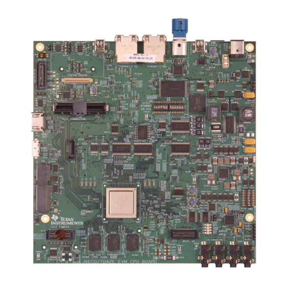
Codec INA/Pwr Measure DDR3L Memory Dual CSI2 Lout 60p MIPI CAM Interface JTAG Codec Audio Figure 2. CPU Board – Front SPRUIB9 – December 2016 DRA72x EVM CPU Board User's Guide Submit Documentation Feedback Copyright © 2016, Texas Instruments Incorporated... -
Page 8: Cpu Board - Back
Overview www.ti.com MicroSD Test Interface Expansion Interface LI Camera LCD Panel Serial Figure 3. CPU Board – Back DRA72x EVM CPU Board User's Guide SPRUIB9 – December 2016 Submit Documentation Feedback Copyright © 2016, Texas Instruments Incorporated... -
Page 9: Hardware
Hardware www.ti.com Hardware Hardware Architecture Figure 4 shows the functional block diagram. Figure 4. CPU Board Block Diagram SPRUIB9 – December 2016 DRA72x EVM CPU Board User's Guide Submit Documentation Feedback Copyright © 2016, Texas Instruments Incorporated... -
Page 10: Power Distribution Block Diagram
• Power Jack: 2.5-mm ID, 5.5-mm OD • Nom voltage: 12 VDC • Max Current: 5000 mA • Efficiency Level V DRA72x EVM CPU Board User's Guide SPRUIB9 – December 2016 Submit Documentation Feedback Copyright © 2016, Texas Instruments Incorporated... -
Page 11: Reset Structure
(SW4) for a complete SoC reset. The other is for warm reset (SW5). The warm reset can also be sourced from the MIPI-60 JTAG/Trace connector. Figure 6. Reset Structure SPRUIB9 – December 2016 DRA72x EVM CPU Board User's Guide Submit Documentation Feedback Copyright © 2016, Texas Instruments Incorporated... -
Page 12: Reset Signals Structure
EMMC by setting the SW5.p3 to ON. Ensure the correct SoC boot mode is set using the SYS_BOOT switches (SW2, SW3). DRA72x EVM CPU Board User's Guide SPRUIB9 – December 2016 Submit Documentation Feedback Copyright © 2016, Texas Instruments Incorporated... -
Page 13: Soc Boot Mode Switch Settings
SW3.P1 GPMC_AD9 (sysboot9) GPMC_D09 SW3.P2 GPMC_AD10 (sysboot10) GPMC_D10 SW3.P3 GPMC_AD11 (sysboot11) GPMC_D11 SW3.P4 GPMC_AD12 (sysboot12) GPMC_D12 SW3.P5 GPMC_AD13 (sysboot13) GPMC_D13 SW3.P6 SPRUIB9 – December 2016 DRA72x EVM CPU Board User's Guide Submit Documentation Feedback Copyright © 2016, Texas Instruments Incorporated... -
Page 14: Board Controls For Memory Booting Options
(LCD panel) pins. Thus, these interfaces cannot be used simultaneously. TI recommends any LCD panel be removed from the system using debug or trace features. DRA72x EVM CPU Board User's Guide SPRUIB9 – December 2016 Submit Documentation Feedback Copyright © 2016, Texas Instruments Incorporated... - Page 15 ID value either high (OFF) or low (ON). 3.11 Wired Ethernet Dual Gigabit Ethernet ports are supported on the EVM. RGMII ports 0 and 1 drive the Texas Instruments DP83867 Gigabit PHYs. The PHYs are configured through the Management Data Input/Output bus (MDIO), with address set to 0x2 (port 0) and 0x3 (port 1).
- Page 16 85 MHz. The interrupt is supported to enable back-channel communication, typically needed if supporting touch screen. The transceiver is configured using I2C (port 5, 0x1B). Serializer device used: Texas Instruments DS90UH925Q Connector used: Automotive HSD Connector, right-angle plug for PCB, Rosenberger D4S20D-40ML5-Z. 3.13 Video Input 3.13.1...
-
Page 17: User Leds
INA226 devices using dedicated I2C buses. The INA226s can be controlled through an off-board module (FTDI USART, MSP430, or a similar device). SPRUIB9 – December 2016 DRA72x EVM CPU Board User's Guide Submit Documentation Feedback Copyright © 2016, Texas Instruments Incorporated... -
Page 18: Power Monitor Mapping
VCCA_IN 10m-Ω Total System power rail 0x48 EVM_12V 10m-Ω Total System 12v power rail 0x49 1v8_PHY2 10m-Ω CPU PHY LDO Rail DRA72x EVM CPU Board User's Guide SPRUIB9 – December 2016 Submit Documentation Feedback Copyright © 2016, Texas Instruments Incorporated... -
Page 19: I2C Device Address Chart
NOTE: Functional signals of pinmux are not consider for this table. For more details, see the DRA72x_TDA2Ex CPU EVM Schematic Rev D (http://www.ti.com/lit/zip/sprr236). SPRUIB9 – December 2016 DRA72x EVM CPU Board User's Guide Submit Documentation Feedback Copyright © 2016, Texas Instruments Incorporated... -
Page 20: I/O Expander Map
MUX out control signal for UART1 vs UART for terminal access MCASP1_ENn COM8 interface level shifter enable signal SEL_UART3_SPI2 MUX out control signal for UART3 Vs SPI2 Open DRA72x EVM CPU Board User's Guide SPRUIB9 – December 2016 Submit Documentation Feedback Copyright © 2016, Texas Instruments Incorporated... -
Page 21: Description
MMC2 DIP Switch Override Enable MMC2_BOOT_OVR MMC2 DIP Switch Override NOR_BOOT_OVR_OEN NOR BOOT DIP Switch Override Enable NOR_BOOT_OVR NOR BOOT DIP Switch Override SPRUIB9 – December 2016 DRA72x EVM CPU Board User's Guide Submit Documentation Feedback Copyright © 2016, Texas Instruments Incorporated... -
Page 22: Eeprom Data Format
Char board_name[16]; Unsigned short version_major; Unsigned short version_minor; Unsigned long config_option; Unsigned long emif1_size_bytes; Unsigned long emif2_size_bytes; Char reserved[28]; } eeprom_id; DRA72x EVM CPU Board User's Guide SPRUIB9 – December 2016 Submit Documentation Feedback Copyright © 2016, Texas Instruments Incorporated... -
Page 23: Signal Multiplex Logic
Use Default NOR Address (default) Use Alternate NOR Address (w/ EMMC) H (RU99) EXP3.P1 Route to COM8Q (MASP3/7) Route to Expansion (McASP3/7)(default) SPRUIB9 – December 2016 DRA72x EVM CPU Board User's Guide Submit Documentation Feedback Copyright © 2016, Texas Instruments Incorporated... -
Page 24: Soc Pinmux For Gpmc And Qspi
Video Input Port (VIN1A): CLK, HSYNC, VSYNC, DE, D[23:0] • Video Output Port (VOUT3): CLK, HSYNC, VSYNC, DE, D[23:0] • Boot Mode Selection (SYSBOOT): SYSBOOT[15:0] DRA72x EVM CPU Board User's Guide SPRUIB9 – December 2016 Submit Documentation Feedback Copyright © 2016, Texas Instruments Incorporated... -
Page 25: Soc Pinmux For Gpmc/Vin1/Vout3
Signal Multiplex Logic www.ti.com Figure 9. SoC Pinmux for GPMC/VIN1/VOUT3 SPRUIB9 – December 2016 DRA72x EVM CPU Board User's Guide Submit Documentation Feedback Copyright © 2016, Texas Instruments Incorporated... -
Page 26: Mux Diagram For Gpmc/Vin1/Vout3
The functions shown are intended to reflect those supported on the EVM. These include: • Memory Bus (GPMC): A[27:19], CS1 • EMMC Memory (MMC2): CLK, CMD, D[7:0] Figure 11. SoC Pinmux for GPMC/EMMC DRA72x EVM CPU Board User's Guide SPRUIB9 – December 2016 Submit Documentation Feedback Copyright © 2016, Texas Instruments Incorporated... -
Page 27: Mux Diagram For Gpmc And Emmc
The functions shown are intended to reflect those supported on the EVM. These include: • Video Input Port (VIN2A): CLK, HSYNC, VSYNC, DE, D[9:0] Figure 13. SoC Pinmux for VIN2A and EMU SPRUIB9 – December 2016 DRA72x EVM CPU Board User's Guide Submit Documentation Feedback Copyright © 2016, Texas Instruments Incorporated... -
Page 28: Mux Diagram For Vin2A And Emu
Gig Ethernet (RGMII1): TXC, TXCTL, TXD[3:0], RXC, RXCTL, RXD[3:0] • Management Data I/O (MDIO): MCLK, D Figure 15. SoC Pinmux for VIN2A and RGMII1 DRA72x EVM CPU Board User's Guide SPRUIB9 – December 2016 Submit Documentation Feedback Copyright © 2016, Texas Instruments Incorporated... -
Page 29: Mux Diagram For Vin2A And Rgmii1
Management Data I/O (MDIO): MCLK, D • Video Input Port (VIN1B): CLK, HSYNC, VSYNC, DE, [7:0] Figure 17. SoC Pinmux for RGMII0 and VIN1B SPRUIB9 – December 2016 DRA72x EVM CPU Board User's Guide Submit Documentation Feedback Copyright © 2016, Texas Instruments Incorporated... -
Page 30: Mux Diagram For Rgmii0 And Vin1B
UART3_TX, _RX, _CTS, _RTS COM8Q Connector SPI2_SCLK, _D[1:0], _CS[0] SPI2 SPI2_SCLK, _D[1:0], _CS[0] Expansion Connector Figure 20. Mux Diagram for SPI2 and UART3 DRA72x EVM CPU Board User's Guide SPRUIB9 – December 2016 Submit Documentation Feedback Copyright © 2016, Texas Instruments Incorporated... -
Page 31: Usb3-Supported Configurations
– Host connects to the EVM acting as a device • Standard-A plug to Micro-B plug – Host connects to the EVM acting as a device SPRUIB9 – December 2016 DRA72x EVM CPU Board User's Guide Submit Documentation Feedback Copyright © 2016, Texas Instruments Incorporated... -
Page 32: Option 1
Option 1: Micro-A Plug to Standard-B Plug Use a USB3.0 micro-A to standard-B and USB3.0 hub, as the SIIG one shown in Figure Figure 23. Option 1 DRA72x EVM CPU Board User's Guide SPRUIB9 – December 2016 Submit Documentation Feedback Copyright © 2016, Texas Instruments Incorporated... -
Page 33: Option 2
Option 2: Micro-A Plug to Micro-B Plug Use a USB3.0 micro-A to micro-B and USB3.0 hub, as the IOGEAR one shown in Figure Figure 24. Option 2 SPRUIB9 – December 2016 DRA72x EVM CPU Board User's Guide Submit Documentation Feedback Copyright © 2016, Texas Instruments Incorporated... -
Page 34: References
DRA72x_TDA2Ex CPU EVM BOM Rev D • DRA72x_TDA2Ex CPU EVM CPU Assembly Drawing Rev D • DRA72x_TDA2Ex CPU EVM CPU PCB Drawing Rev D DRA72x EVM CPU Board User's Guide SPRUIB9 – December 2016 Submit Documentation Feedback Copyright © 2016, Texas Instruments Incorporated... - Page 35 STANDARD TERMS AND CONDITIONS FOR EVALUATION MODULES Delivery: TI delivers TI evaluation boards, kits, or modules, including demonstration software, components, and/or documentation which may be provided together or separately (collectively, an “EVM” or “EVMs”) to the User (“User”) in accordance with the terms and conditions set forth herein.
- Page 36 FCC Interference Statement for Class B EVM devices NOTE: This equipment has been tested and found to comply with the limits for a Class B digital device, pursuant to part 15 of the FCC Rules. These limits are designed to provide reasonable protection against harmful interference in a residential installation.
- Page 37 【無線電波を送信する製品の開発キットをお使いになる際の注意事項】 開発キットの中には技術基準適合証明を受けて いないものがあります。 技術適合証明を受けていないもののご使用に際しては、電波法遵守のため、以下のいずれかの 措置を取っていただく必要がありますのでご注意ください。 1. 電波法施行規則第6条第1項第1号に基づく平成18年3月28日総務省告示第173号で定められた電波暗室等の試験設備でご使用 いただく。 2. 実験局の免許を取得後ご使用いただく。 3. 技術基準適合証明を取得後ご使用いただく。 なお、本製品は、上記の「ご使用にあたっての注意」を譲渡先、移転先に通知しない限り、譲渡、移転できないものとします。 上記を遵守頂けない場合は、電波法の罰則が適用される可能性があることをご留意ください。 日本テキサス・イ ンスツルメンツ株式会社 東京都新宿区西新宿6丁目24番1号 西新宿三井ビル 3.3.3 Notice for EVMs for Power Line Communication: Please see http://www.tij.co.jp/lsds/ti_ja/general/eStore/notice_02.page 電力線搬送波通信についての開発キットをお使いになる際の注意事項については、次のところをご覧ください。http:/ /www.tij.co.jp/lsds/ti_ja/general/eStore/notice_02.page SPACER EVM Use Restrictions and Warnings: 4.1 EVMS ARE NOT FOR USE IN FUNCTIONAL SAFETY AND/OR SAFETY CRITICAL EVALUATIONS, INCLUDING BUT NOT LIMITED TO EVALUATIONS OF LIFE SUPPORT APPLICATIONS.
- Page 38 Notwithstanding the foregoing, any judgment may be enforced in any United States or foreign court, and TI may seek injunctive relief in any United States or foreign court. Mailing Address: Texas Instruments, Post Office Box 655303, Dallas, Texas 75265 Copyright © 2016, Texas Instruments Incorporated...
- Page 39 IMPORTANT NOTICE Texas Instruments Incorporated and its subsidiaries (TI) reserve the right to make corrections, enhancements, improvements and other changes to its semiconductor products and services per JESD46, latest issue, and to discontinue any product or service per JESD48, latest issue.
Need help?
Do you have a question about the DRA72 Series and is the answer not in the manual?
Questions and answers