Table of Contents
Advertisement
Quick Links
DRV8834 Evaluation Module
This document is provided as a supplement to the
implementation of the DRV8834 customer evaluation module (EVM).
...................................................................................................................
1
2
2.1
2.2
2.3
2.4
2.5
3
3.1
3.2
4
4.1
4.2
4.3
4.4
4.5
4.6
4.7
4.8
5
5.1
5.2
Trademarks
Windows is a registered trademark of Microsoft corporation.
All other trademarks are the property of their respective owners.
SLVU701B - March 2012 - Revised July 2019
Submit Documentation Feedback
................................................................................................................
..................................................................................................
..........................................................................................................
..............................................................................................................
.............................................................................................................
.......................................................................................................
..................................................................................................
..............................................................................................
..............................................................................................
.................................................................................................
..............................................................................................
.....................................................................................
.............................................................................................
.....................................................................................................
................................................................................
....................................................................................................
................................................................................................
.........................................................................................
.........................................................................................................
....................................................................................................
Copyright © 2012-2019, Texas Instruments Incorporated
SLVU701B - March 2012 - Revised July 2019
DRV8834
datasheet. It details the hardware
Contents
...........................................................
User's Guide
DRV8834 Evaluation Module
2
2
3
3
4
4
4
4
4
4
15
16
18
18
19
20
20
21
22
24
24
26
1
Advertisement
Table of Contents

Related Manuals for Texas Instruments DRV8834EVM


Summary of Contents for Texas Instruments DRV8834EVM
-
Page 1: Table Of Contents
Bill of Materials Trademarks Windows is a registered trademark of Microsoft corporation. All other trademarks are the property of their respective owners. SLVU701B – March 2012 – Revised July 2019 DRV8834 Evaluation Module Submit Documentation Feedback Copyright © 2012–2019, Texas Instruments Incorporated... -
Page 2: Introduction
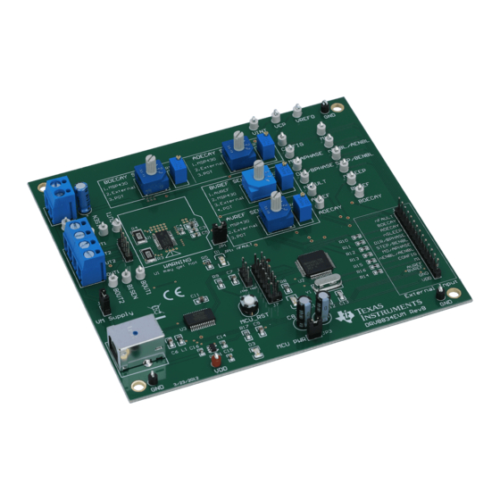
ADECAY Config Config Switch Switch BVREF Test Config Points Switch DRV8834 AVREF Config Switch USB Chip Conn MSP430 3.3V LDO DRV8834 Evaluation Module SLVU701B – March 2012 – Revised July 2019 Submit Documentation Feedback Copyright © 2012–2019, Texas Instruments Incorporated... -
Page 3: Power Connectors
Power Connectors The DRV8834EVM offers access to VM (motor voltage) power rail via a terminal block (J1). A set of test clips in parallel with the terminal block allows for the monitoring of the input power rail. User must apply VM according to datasheet recommended parameters. -
Page 4: Jumpers
Block Diagram www.ti.com Jumpers The DRV8834EVM module contains three 2-pin jumpers which the user can remove in order modify certain aspects of configuration. • JP1: Place a shunt to enable the D1 LED signaling of any fault occurrence. • JP3: Place a shunt to allow 3.3-V supply to the microcontroller. Remove the shunt to disable MSP430 microcontroller and use external microcontroller of choice. - Page 5 3. In the newly open installation pop-up window, click Next. The license agreement will be displayed. Please, read through it carefully and enable the "I Accept the Agreement" radio button and press Next. SLVU701B – March 2012 – Revised July 2019 DRV8834 Evaluation Module Submit Documentation Feedback Copyright © 2012–2019, Texas Instruments Incorporated...
- Page 6 Next button. Figure 5. NI License Agreement 5. Set the default directory for the GUI Installation and click Next. DRV8834 Evaluation Module SLVU701B – March 2012 – Revised July 2019 Submit Documentation Feedback Copyright © 2012–2019, Texas Instruments Incorporated...
- Page 7 Configure the proxy settings as required. This screen is to download the LabVIEW RTE 2014 from ni.com, Click Next to continue the installation. SLVU701B – March 2012 – Revised July 2019 DRV8834 Evaluation Module Submit Documentation Feedback Copyright © 2012–2019, Texas Instruments Incorporated...
- Page 8 9. If the LabVIEW RTE 2014 is selected as a component to install, LabVIEW RTE downloads and performs a silent mode installation. DRV8834 Evaluation Module SLVU701B – March 2012 – Revised July 2019 Submit Documentation Feedback Copyright © 2012–2019, Texas Instruments Incorporated...
- Page 9 Figure 11. LabVIEW RTE Self Extraction 11. A screen appears as shown in Figure 12. It initializes the LabVIEW RTE Installation. SLVU701B – March 2012 – Revised July 2019 DRV8834 Evaluation Module Submit Documentation Feedback Copyright © 2012–2019, Texas Instruments Incorporated...
- Page 10 Figure 12. LabVIEW RTE Installation Initialization 12. A display as shown in Figure 13 appears which indicates the progress of LabVIEW RTE installation. DRV8834 Evaluation Module SLVU701B – March 2012 – Revised July 2019 Submit Documentation Feedback Copyright © 2012–2019, Texas Instruments Incorporated...
- Page 11 13. Once the LabVIEW RTE 2014 is installed, DRV 8834 EVM GUI component installs. 14. After DRV8834 Installation, FTDI Installation begins. A screen as shown in Figure 14 appears, click Extract to proceed. SLVU701B – March 2012 – Revised July 2019 DRV8834 Evaluation Module Submit Documentation Feedback Copyright © 2012–2019, Texas Instruments Incorporated...
- Page 12 Figure 14. FTDI Installation Initialization 15. A screen as shown in Figure 15 appears, click Next to proceed. Figure 15. Driver Installation Wizard DRV8834 Evaluation Module SLVU701B – March 2012 – Revised July 2019 Submit Documentation Feedback Copyright © 2012–2019, Texas Instruments Incorporated...
- Page 13 17. Read through the License Agreement carefully and enable the “I Accept this Agreement” radio button and Click on Next. Figure 16. License Agreement for FTDI Driver 18. Click Finish to complete the Driver Installation. SLVU701B – March 2012 – Revised July 2019 DRV8834 Evaluation Module Submit Documentation Feedback Copyright © 2012–2019, Texas Instruments Incorporated...
- Page 14 Figure 18. Installation Complete 20. A Readme window as shown in Figure 19 appears displaying the link for LV 2014 RTE. DRV8834 Evaluation Module SLVU701B – March 2012 – Revised July 2019 Submit Documentation Feedback Copyright © 2012–2019, Texas Instruments Incorporated...
-
Page 15: The Windows Application
The Windows Application The DRV8834EVM Windows application is the software counterpart for the DRV8834 EVM. It allows the PC computer to connect to the MSP430F2617 microcontroller though an USB interface chip. Once connection is established and commands are sent, microcontroller takes care of configuring control signals and administering certain levels of automation, such as microstepping coordination, stepping rate acceleration and deceleration, ITrip configuration and PWM generation. -
Page 16: Dual H Bridge Mode
The Windows Application www.ti.com Figure 20. DRV8834EVM.exe Main Screen All the control signals needed to control motor enablement (nENABLE or ENABLEx), direction of rotation (PHASEx or DIR), current control (VREFx) and PWM control for both enablement and direction control signals are made available throughout one of the three control tabs. - Page 17 The algorithms offer accurate acceleration and deceleration profiles which help in the obtaining of better motion quality and performance. SLVU701B – March 2012 – Revised July 2019 DRV8834 Evaluation Module Submit Documentation Feedback Copyright © 2012–2019, Texas Instruments Incorporated...
-
Page 18: The Config Control Signal
Failure to properly set these switches will result in problems with the current regulation and stepper motor functioning. DRV8834 Evaluation Module SLVU701B – March 2012 – Revised July 2019 Submit Documentation Feedback Copyright © 2012–2019, Texas Instruments Incorporated... -
Page 19: Menu Options
– The About Page provides the details like the Name of the GUI, GUI version, Supported OS and Copyright Information. SLVU701B – March 2012 – Revised July 2019 DRV8834 Evaluation Module Submit Documentation Feedback Copyright © 2012–2019, Texas Instruments Incorporated... -
Page 20: Drv8834 Gpio Control Signals
DAC digital value from 0 to 4095, changes the analog voltage at the respective VREF pin from 0 V to 2.5 V respectively. See Equation DRV8834 Evaluation Module SLVU701B – March 2012 – Revised July 2019 Submit Documentation Feedback Copyright © 2012–2019, Texas Instruments Incorporated... -
Page 21: Stepper Control
SLVU701B – March 2012 – Revised July 2019 DRV8834 Evaluation Module Submit Documentation Feedback Copyright © 2012–2019, Texas Instruments Incorporated... -
Page 22: Move Steps Frame
If steps to stop is larger than the number of steps, then the motor stops abruptly and without undergoing a deceleration profile. DRV8834 Evaluation Module SLVU701B – March 2012 – Revised July 2019 Submit Documentation Feedback Copyright © 2012–2019, Texas Instruments Incorporated... - Page 23 512 degrees of microstepping are obtained, depending on the chosen operating mode. SLVU701B – March 2012 – Revised July 2019 DRV8834 Evaluation Module Submit Documentation Feedback Copyright © 2012–2019, Texas Instruments Incorporated...
-
Page 24: Schematics And Bill Of Materials
Schematics and Bill of Materials Schematics The following pages contain the schematics for the DRV8834EVM. The DRV8834EVM schematics are also available in the form of a PDF file (SCH.pdf) inside the EVM_Related folder on the downloadable EVM software package. TP10... - Page 25 Texas Instruments 2.2uF BYPASS DRV8834DC and SteppingMotor Drive EVM Volt_RegLP2985 .01uF 3.3V Size FCSMNo. DWGNo. Scale Sheet 2 of 2 SLVU701B – March 2012 – Revised July 2019 DRV8834 Evaluation Module Submit Documentation Feedback Copyright © 2012–2019, Texas Instruments Incorporated...
-
Page 26: Bill Of Materials
TP15, TP16, TP17, TP18, TP19, TP20, TP21 TP22 Glass Beaded Test Point Kobiconn 151-107-RC WHITE TP23 Glass Beaded Test Point Kobiconn 151-107-RC DRV8834 Evaluation Module SLVU701B – March 2012 – Revised July 2019 Submit Documentation Feedback Copyright © 2012–2019, Texas Instruments Incorporated... - Page 27 MFG PART NUMBER VALUE QUANTITY TP24, TP25, TP26, Glass Beaded Test Point Kobiconn 151-103-RC BLACK TP27 Stepping and DC motor Driver Texas Instruments IC MCU 16BIT 55K FLASH Texas Instruments MSP430F2617TPMR MSP430 MCU 64-LQFP USB Chip FTDI FT232RL R USB Driver CRYSTAL 8.00 MHZ 20PF...
- Page 28 TI products. TI’s provision of these resources does not expand or otherwise alter TI’s applicable warranties or warranty disclaimers for TI products. Mailing Address: Texas Instruments, Post Office Box 655303, Dallas, Texas 75265 Copyright © 2019, Texas Instruments Incorporated...
Need help?
Do you have a question about the DRV8834EVM and is the answer not in the manual?
Questions and answers