Table of Contents
Advertisement
Quick Links
www.ti.com
User's Guide
DRV8329AEVM User's Guide
This document is provided with the
DRV8329 data sheet
(DRV8329 4.5-V to 60-V 1000/2000mA 3-phase gate
implementation of the EVM and shows how to set up and power the board.
The DRV8329AEVM comes automatically populated with and configured for the DRV8329A. It is also
compatible for the DRV8329B variants (see
DRV8329A with the DRV8329B for compatibility.
Warnings..........................................................................................................................................................3
2
Introduction.............................................................................................................................................................................4
Guide....................................................................................................................................................................6
4.2 Connection Details.............................................................................................................................................................
Lights........................................................................................................................................................................10
4.5 Interfacing DRV8329AEVM and LAUNCHXL-F280049C LaunchPad.............................................................................
5 Hardware Setup....................................................................................................................................................................
Application.............................................................................................................................................16
DRV8329AEVM-GUI...........................................................................................................................16
6.2 DRV8329x EVM GUI Quick Start Guide..........................................................................................................................
DRV8329AEVM-GUI........................................................................................................................................17
7
Schematics............................................................................................................................................................................19
7.1
DRV8329A/B....................................................................................................................................................................19
7.2 Status LEDs.....................................................................................................................................................................
7.4 Power Stage and MOSFETs............................................................................................................................................
7.5 Main Supply Input............................................................................................................................................................
7.6 Hall Sensor and Hall Power selection..............................................................................................................................
7.7 Connectors, Selectors, and Analog Control Interface......................................................................................................
7.8 Dead Time and CSA Gain Selection................................................................................................................................
Protection..........................................................................................................................................23
Figure 4-2. Connections from motor to DRV8329AEVM.............................................................................................................
Figure 4-3. DRV8329AEVM on headers J1/J3 and J2/J4 of LaunchPad....................................................................................
Figure 4-4. Micro-USB plugged into LaunchPad.........................................................................................................................
Figure 4-5. DRV8329AEVM LEDs.............................................................................................................................................
Figure 4-6. User-adjustable jumpers, resistors, and switches on DRV8329AEVM...................................................................
Figure 7-1. DRV8329A/B schematic..........................................................................................................................................
Figure 7-2. Status LEDs schematic...........................................................................................................................................
SLVUCF5 - MARCH 2022
Submit Document Feedback
DRV8329 customer evaluation module (EVM)
Section
Table of Contents
Overview.........................................................................................................................................7
Functions............................................................................................................11
Connections........................................................................................................................20
List of Figures
Layout.....................................................................................................................................5
DRV8329AEVM..........................................................................................................7
message................................................................................................................................16
connected....................................................................................................17
Copyright © 2022 Texas Instruments Incorporated
ABSTRACT
driver). This User's Guide details the
Note
4.4.1), but the user will need to replace the
LAUNCHXL-F280049C................................................................7
Gallery.........................................................................16
Table of Contents
as a supplement to the
DRV8329AEVM User's Guide
7
12
15
17
19
20
21
21
22
22
8
9
9
10
12
19
19
1
Advertisement
Table of Contents

Related Manuals for Texas Instruments DRV8329AEVM


Summary of Contents for Texas Instruments DRV8329AEVM
-
Page 1: Table Of Contents
This User's Guide details the implementation of the EVM and shows how to set up and power the board. Note The DRV8329AEVM comes automatically populated with and configured for the DRV8329A. It is also compatible for the DRV8329B variants (see Section 4.4.1), but the user will need to replace the... - Page 2 List of Tables Table 2-1. DRV8329 device variant names and descriptions (default of EVM in bold)..............4 Table 4-1. Description of DRV8329AEVM LEDs (on during power up in bold)................10 Table 4-2. User-Selectable Jumpers............................Table 4-3. Connections for Header J1 on DRV8329AEVM (DNP in bold).................
-
Page 3: Cautions And Warnings
Read the User's Guide before use. HOT SURFACE: Caution Hot Surface! Contact may cause burns. Do not touch. Please take the proper precautions when operating. SLVUCF5 – MARCH 2022 DRV8329AEVM User’s Guide Submit Document Feedback Copyright © 2022 Texas Instruments Incorporated... -
Page 4: Introduction
DRV8329 to control the BLDC motor. This document serves as a startup guide to supplement the DRV8329AEVM + LAUNCHXL-F280049C BLDC motor control demo kit. It also is intended to help engineers design, implement, and validate reference hardware and software for the LaunchPad MCU and DRV8329. -
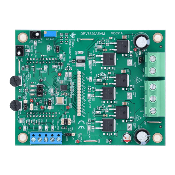
Page 5: Figure 2-1. Drv8329Aevm Pcb Layout
Introduction Figure 2-1. DRV8329AEVM PCB Layout SLVUCF5 – MARCH 2022 DRV8329AEVM User’s Guide Submit Document Feedback Copyright © 2022 Texas Instruments Incorporated... -
Page 6: Quick Start Guide
3 Quick Start Guide The DRV8329AEVM requires a power supply with a recommended operating range from 4.5-V to 60-V. To setup and power the EVM, follow the sequence below: 1. Connect the power supply ground to the GND of the 2-pin power connector J10 and the power supply positive terminal to the PVDD pin of J10. -
Page 7: Hardware And Software Overview
4.2 Connection Details Figure 4-2 shows the power supply and motor connections made to the DRV8329AEVM in order to spin a 3-phase sensored or sensorless Brushless-DC motor. A 4.5-V to 60-V power supply or battery is connected to the PVDD and GND terminals. The three phases of the BLDC motor connect directly to the OUTA, OUTB, and OUTC terminals of the screw terminal J13 provided on the DRV8329AEVM. -
Page 8: Figure 4-2. Connections From Motor To Drv8329Aevm
Micro-USB cable is plugged in to the LAUNCHXL-F280049C to provide communication between the LaunchPad firmware and GUI as well as the correct installment of the DRV8329AEVM to the J1/J3 and J2/J4 headers of the LaunchPad. DRV8329AEVM User’s Guide SLVUCF5 –... -
Page 9: Figure 4-3. Drv8329Aevm On Headers J1/J3 And J2/J4 Of Launchpad
Hardware and Software Overview Figure 4-3. DRV8329AEVM on headers J1/J3 and J2/J4 of LaunchPad Figure 4-4. Micro-USB plugged into LaunchPad SLVUCF5 – MARCH 2022 DRV8329AEVM User’s Guide Submit Document Feedback Copyright © 2022 Texas Instruments Incorporated... -
Page 10: Led Lights
USB cable is plugged in to the LaunchPad. The DRV8329AEVM has 4 status LEDs on the board. By default, the PVDD and AVDD LEDs will light up when the board is powered on. The fault LED will light up when the driver reports a fault, and the MCU LED (tied to GPIO59) can be used for debugging and validation. -
Page 11: Drv8329Aevm Configurability Switch Functions
Hardware and Software Overview 4.4 DRV8329AEVM Configurability Switch Functions The DRV8329AEVM includes a variety of user-selectable jumpers and unpopulated components on the PCB to choose user settings and evaluate the DRV8329A, DRV8329B, DRV8329C, or DRV8329D device. A summary of those selectable settings is listed in... -
Page 12: Interfacing Drv8329Aevm And Launchxl-F280049C Launchpad
Figure 4-6. User-adjustable jumpers, resistors, and switches on DRV8329AEVM 4.4.1 DRV8329A/B Compatibility The DRV8329AEVM default is the DRV8329A (Hardware variant), but can also be compatible with the DRV8329B. The main difference is that DRV8329A operates in 6x PWM mode and DRV8329B operates in 3x PWM mode. -
Page 13: Table 4-4. Connections For Header J2 On
Hardware and Software Overview Table 4-3. Connections for Header J1 on DRV8329AEVM (DNP in bold) (continued) J3 Pin Number DRV8329AEVM Function LAUNCHXL-F280049C Function Description POT_MCU/NC_49C PGA1/3/5_GND Not used GND connection Not used GPIO13/SCIBRX Not used VSENA ADCINA5 Phase A Voltage Sense... - Page 14 Hardware and Software Overview www.ti.com Table 4-4. Connections for Header J2 on DRV8329AEVM (continued) J4 Pin Number DRV8329AEVM Function LAUNCHXL-F280049C Function Description Not used SPIASOMI Not used nSLEEP_49C GPIO30 nSLEEP signal (active low) DRVOFF GPIO39 Active-high output to disable gate...
-
Page 15: Hardware Setup
The hardware required to run the motor control is the LAUNCHXL-F280049C LaunchPad development kit, the DRV8329AEVM, a Micro-USB cable, and a power supply with a DC output from 4.5-V to 60-V. Follow these steps to set up the evaluation module: 1. -
Page 16: Firmware And Gui Application
6 Firmware and GUI Application The DRV8329AEVM can implement sensored, sensorless, or Field-oriented control for commutating a 3-phase Brushless-DC motor. There are two GUIs to support DRV8329A (DRV8329A-EVM-GUI) and DRV8329B (DRV8329B-EVM-GUI) using sensored trapezoidal commutation with Hall sensor feedback. The GUIs allow for basic trapezoidal motor control functions such as acceleration, duty cycle control, PWM switching frequency, MCU dead time insertion, braking, and direction changes. -
Page 17: Drv8329X Evm Gui Quick Start Guide
9. If R69 is populated, use the DRVOFF switch to shut off the gate drivers and Hi-Z the gate driver outputs. 6.3 Using the DRV8329AEVM-GUI The GUI offers the following features: MOTOR CONTROL SETTINGS SLVUCF5 – MARCH 2022 DRV8329AEVM User’s Guide Submit Document Feedback Copyright © 2022 Texas Instruments Incorporated... - Page 18 PVDD Undervoltage Fault – PVDD is under 4.5 V. Configurable through firmware. Over-Current – Measured LSS current is over the Over-Current threshold. DRV8329 Fault – Fault indicated by the DRV8329. See DRV8329 datasheet. DRV8329AEVM User’s Guide SLVUCF5 – MARCH 2022 Submit Document Feedback Copyright © 2022 Texas Instruments Incorporated...
-
Page 19: Schematics
Schematics 7 Schematics 7.1 DRV8329A/B Figure 7-1. DRV8329A/B schematic 7.2 Status LEDs Figure 7-2. Status LEDs schematic SLVUCF5 – MARCH 2022 DRV8329AEVM User’s Guide Submit Document Feedback Copyright © 2022 Texas Instruments Incorporated... -
Page 20: Launchpad Connectors And Connections
7.3 LaunchPad Connectors and Connections Figure 7-3. LaunchPad connectors schematic Figure 7-4. LaunchPad connections schematic 7.4 Power Stage and MOSFETs Figure 7-5. Powerstage and MOSFETs schematic DRV8329AEVM User’s Guide SLVUCF5 – MARCH 2022 Submit Document Feedback Copyright © 2022 Texas Instruments Incorporated... -
Page 21: Main Supply Input
7.5 Main Supply Input Figure 7-6. Main supply input schematic 7.6 Hall Sensor and Hall Power selection Figure 7-7. Hall Sensor and Hall Power selection schematic SLVUCF5 – MARCH 2022 DRV8329AEVM User’s Guide Submit Document Feedback Copyright © 2022 Texas Instruments Incorporated... -
Page 22: Connectors, Selectors, And Analog Control Interface
Figure 7-8. Connectors, Selectors, and Analog Control Interface schematic 7.8 Dead Time and CSA Gain Selection Figure 7-9. Dead time and CSA gain selection schematic DRV8329AEVM User’s Guide SLVUCF5 – MARCH 2022 Submit Document Feedback Copyright © 2022 Texas Instruments Incorporated... -
Page 23: Voltage Sense And Protection
Schematics 7.9 Voltage Sense and Protection Figure 7-10. Voltage Sense and Protection schematic SLVUCF5 – MARCH 2022 DRV8329AEVM User’s Guide Submit Document Feedback Copyright © 2022 Texas Instruments Incorporated... - Page 24 TI products. TI’s provision of these resources does not expand or otherwise alter TI’s applicable warranties or warranty disclaimers for TI products. TI objects to and rejects any additional or different terms you may have proposed. IMPORTANT NOTICE Mailing Address: Texas Instruments, Post Office Box 655303, Dallas, Texas 75265 Copyright © 2022, Texas Instruments Incorporated...
Need help?
Do you have a question about the DRV8329AEVM and is the answer not in the manual?
Questions and answers