Table of Contents
Advertisement
Quick Links
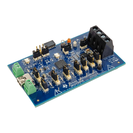
DRV2700EVM High Voltage Piezo Driver Evaluation Kit
The DRV2700 is a single-chip, high-voltage piezo driver with an integrated 105-V boost switch, integrated
power diode, and integrated fully differential amplifier. This evaluation kit demonstrates:
•
Multiple input modes including: 0- to 10-V single ended, PWM, and AC input modes
•
Multiple output modes including: 0- to 200-Vpp differential, 0- to 105-V single and multiple ended
•
2 power supply inputs to isolate power consumption on DRV2700
•
8 convenient boost voltage settings and 4 different gain settings
•
Small footprint (9 mm x 13 mm)
•
Breakout for usage as a boost converter
The evaluation kit is designed for all-around use and can be used not only for evaluation but can also be
used for prototyping into systems. The EVM also contains a microcontroller, LDO (3.3 V) and LEDs for
status and input settings.
Evaluation Kit Contents:
•
DRV2700EVM evaluation board
•
Demonstration mode firmware preloaded onto microcontroller
•
Downloadable software to control EVM
•
Mini-B USB cable
Needed for programming and advanced configuration:
•
Code Composer Studio™ (CCS) or IAR Embedded Workbench IDE for MSP430
•
MSP430 LaunchPad™ (MSP-EXP430G2) or MSP430-FET430UIF hardware programming tool
•
DRV2700EVM firmware available on the
•
MSP-JTAG2SBW JTAG to Spy-Bi-Wire adapter
SLOU403C – March 2015 – Revised June 2018
Submit Documentation Feedback
DRV2700EVM tool folder
Copyright © 2015–2018, Texas Instruments Incorporated
SLOU403C – March 2015 – Revised June 2018
DRV2700EVM High Voltage Piezo Driver Evaluation Kit
User's Guide
1
Advertisement
Table of Contents

Subscribe to Our Youtube Channel
Related Manuals for Texas Instruments DRV2700EVM


Summary of Contents for Texas Instruments DRV2700EVM
- Page 1 User's Guide SLOU403C – March 2015 – Revised June 2018 DRV2700EVM High Voltage Piezo Driver Evaluation Kit The DRV2700 is a single-chip, high-voltage piezo driver with an integrated 105-V boost switch, integrated power diode, and integrated fully differential amplifier. This evaluation kit demonstrates: •...
-
Page 2: Table Of Contents
Floating Reference at 3 Hz and No Load ................Floating Reference at 1 Hz and No Load ....................DC Coupled Input Diagram DRV2700EVM High Voltage Piezo Driver Evaluation Kit SLOU403C – March 2015 – Revised June 2018 Submit Documentation Feedback Copyright © 2015–2018, Texas Instruments Incorporated... - Page 3 And may require export or re-export license for shipping it in compliance with the applicable regulations of certain countries. SLOU403C – March 2015 – Revised June 2018 DRV2700EVM High Voltage Piezo Driver Evaluation Kit Submit Documentation Feedback Copyright © 2015–2018, Texas Instruments Incorporated...
- Page 4 Danger High Voltage! Electric shock possible when connecting board to live wire. Board should be handled with care by a professional. For safety, use of isolated test equipment with overvoltage/overcurrent protection is highly recommended. DRV2700EVM High Voltage Piezo Driver Evaluation Kit SLOU403C – March 2015 – Revised June 2018 Submit Documentation Feedback...
- Page 5 Any other use and/or application are strictly prohibited by Texas Instruments. If you are not suitable qualified, you should immediately stop from further use of the HV EVM.
-
Page 6: Getting Started
Figure 1 shows the names and locations of the various elements on the EVM. To power the board, connect the DRV2700EVM to an available USB port on your computer using a mini-B USB cable. The default board settings cause the microcontroller (MSP430) to control the inputs of the DRV2700 at power up. The MSP430 has each of these control settings low which disables the DRV2700, by default. -
Page 7: Quick Start Board Setup
Quick Start Board Setup The DRV2700EVM comes with preprogrammed firmware to provide a 0- to 200-Vpp signal between OUT+ and OUT–. 1. Out of the box, the jumpers are set to begin demo mode using USB power. The default jumper settings... -
Page 8: Overview Of Evm
USB power and the DRV jumper (JP11) with VIN. With this configuration, measuring the provided voltage and current into VIN gives the power consumption of the DRV2700. DRV2700EVM High Voltage Piezo Driver Evaluation Kit SLOU403C – March 2015 – Revised June 2018 Submit Documentation Feedback Copyright ©... -
Page 9: En And Gain Configuration
MSP430 of 0–3.3 V, 300 Hz and 50% duty cycle. Figure 3. Gain = 40.7 dB Figure 4. Gain = 38.4 dB SLOU403C – March 2015 – Revised June 2018 DRV2700EVM High Voltage Piezo Driver Evaluation Kit Submit Documentation Feedback Copyright © 2015–2018, Texas Instruments Incorporated... -
Page 10: Inputs
PWM, Analog, and Single-Ended Inputs, for more information. Outputs The DRV2700EVM has 4 referenced outputs (BST, OUT–, OUT+, and GND). They are output from a terminal block to mitigate touching between two high voltage lines. See the Output section for additional information. -
Page 11: Evm Control Software (Gui)
EVM Control Software (GUI) www.ti.com EVM Control Software (GUI) By default, the DRV2700EVM can be controlled programmatically through the GUI Interface. Figure 7 is a screenshot of the GUI. Run the GUI by downloading it from the DRV2700 product page, installing the GUI and then running it. -
Page 12: Boost Converter
Before connecting the load, ensure the load is rated for the current boost voltage setting. Boost Voltage Setting Resistors for more information on how to set the boost voltage. DRV2700EVM High Voltage Piezo Driver Evaluation Kit SLOU403C – March 2015 – Revised June 2018 Submit Documentation Feedback... -
Page 13: Boost Voltage Setting Resistors
If another voltage is desired, replace R1 and R5 using Equation 1 and leave JP2–4 disconnected. SLOU403C – March 2015 – Revised June 2018 DRV2700EVM High Voltage Piezo Driver Evaluation Kit Submit Documentation Feedback Copyright © 2015–2018, Texas Instruments Incorporated... -
Page 14: Disconnecting Bst/Pvdd
105 V. The selected capacitor should have a minimum derated capacitance of 50 nF. Figure 13 for a diagram of the input configuration. DRV2700EVM High Voltage Piezo Driver Evaluation Kit SLOU403C – March 2015 – Revised June 2018 Submit Documentation Feedback Copyright © 2015–2018, Texas Instruments Incorporated... -
Page 15: Pwm, Analog, And Single-Ended Inputs
When using the DRV2700EVM in MSP430 PWM input mode, the onboard MSP430 generates a differential PWM signal that is sent through a low-pass filter to the DRV2700. The DRV2700EVM is setup to use this mode by default. Set to default settings to use this input mode. -
Page 16: External Analog (Ac Coupled) Input
4. Connect the positive terminal of the input signal source to AIN+ and the negative terminal to AIN– 5. Enable the power supply Single-Ended (DC Coupled) Input The DRV2700EVM can be operated with a DC input. There are two configurations available in this EVM that show: •... -
Page 17: Set Reference To External 2.5 V
EVM powered through USB (5 V). Figure 13 for a diagram of the input configuration. SLOU403C – March 2015 – Revised June 2018 DRV2700EVM High Voltage Piezo Driver Evaluation Kit Submit Documentation Feedback Copyright © 2015–2018, Texas Instruments Incorporated... -
Page 18: Dc Coupled Input Diagram
INí Network Reference Voltage Not Used in Floating Reference Config Figure 13. DC Coupled Input Diagram DRV2700EVM High Voltage Piezo Driver Evaluation Kit SLOU403C – March 2015 – Revised June 2018 Submit Documentation Feedback Copyright © 2015–2018, Texas Instruments Incorporated... -
Page 19: Output
DRV2700 100 Vp Element OUT+ Piezo 100 Vp Element Figure 15. Two Terminal Single Ended Output SLOU403C – March 2015 – Revised June 2018 DRV2700EVM High Voltage Piezo Driver Evaluation Kit Submit Documentation Feedback Copyright © 2015–2018, Texas Instruments Incorporated... -
Page 20: Load Selection
300 Hz). For more information, see the Piezo Load Selection section of the DRV2700 data sheet (SLOS861). Figure 13 for a diagram of the input configuration. DRV2700EVM High Voltage Piezo Driver Evaluation Kit SLOU403C – March 2015 – Revised June 2018 Submit Documentation Feedback Copyright © 2015–2018, Texas Instruments Incorporated... -
Page 21: Filtering And Adapting Pwm Waveforms
Filtering and Adapting PWM Waveforms The DRV2700EVM has the capability to support many different input filter configurations. Depending on the input mode, input frequency, and input voltage, the filter can be adapted to attenuate any undesired out-of-band content. This section describes the input filter requirements and the various respective configurations. -
Page 22: Filter Selection Criteria
Figure 19. Frequency Response of the First-Order Filter DRV2700EVM High Voltage Piezo Driver Evaluation Kit SLOU403C – March 2015 – Revised June 2018 Submit Documentation Feedback Copyright © 2015–2018, Texas Instruments Incorporated... -
Page 23: Differential, Second-Order Filter
Figure 21. Frequency Response of the Second-Order Filter SLOU403C – March 2015 – Revised June 2018 DRV2700EVM High Voltage Piezo Driver Evaluation Kit Submit Documentation Feedback Copyright © 2015–2018, Texas Instruments Incorporated... - Page 24 3. Remove capacitors C8, C9, C13, and C14. Do not remove ac coupling capacitors C4 and C5. Figure 13 for a diagram of the input configuration. DRV2700EVM High Voltage Piezo Driver Evaluation Kit SLOU403C – March 2015 – Revised June 2018 Submit Documentation Feedback...
-
Page 25: Reference
Reference www.ti.com Reference This section includes the DRV2700EVM schematic, PCB Layout, and Bill of Materials. Schematic Figure 22 illustrates the DRV2700EVM schematic. JP12 DC_IN VDRV 10.0k PVDD 0.1µF PVDD 0.1µF VDRV VBUS 10.0k 2.7A 4.7µH 5.6V 0.1µF JP13 GAIN1 GAIN1 0.1uF... -
Page 26: Pcb Layout
Figure 27 show the DRV2700EVM PCB layouts. Figure 23. All Layers Figure 24. Top Layer DRV2700EVM High Voltage Piezo Driver Evaluation Kit SLOU403C – March 2015 – Revised June 2018 Submit Documentation Feedback Copyright © 2015–2018, Texas Instruments Incorporated... -
Page 27: Mid Layer
Reference www.ti.com Figure 25. Mid Layer 1 Figure 26. Mid Layer 2 SLOU403C – March 2015 – Revised June 2018 DRV2700EVM High Voltage Piezo Driver Evaluation Kit Submit Documentation Feedback Copyright © 2015–2018, Texas Instruments Incorporated... -
Page 28: Bill Of Materials
39544-3004 Molex Sullins Connector JP2–JP6, JP12, JP13 Header, 100mil, 2x1, Tin, TH Header,2 Pin,100mil,Tin PEC02SAAN Solutions DRV2700EVM High Voltage Piezo Driver Evaluation Kit SLOU403C – March 2015 – Revised June 2018 Submit Documentation Feedback Copyright © 2015–2018, Texas Instruments Incorporated... - Page 29 3.2x0.55x2.5mm Abracon Corporation B4Y-T Trademarks Code Composer Studio, LaunchPad are trademarks of Texas Instruments. All other trademarks are the property of their respective owners. SLOU403C – March 2015 – Revised June 2018 DRV2700EVM High Voltage Piezo Driver Evaluation Kit Submit Documentation Feedback...
- Page 30 Page ........• Added: "MSP-JTAG2SBW JTAG to Spy-Bi-Wire adapter" to the advanced configuration list • Deleted sentence: "The DRV2700EVM kit includes a JTAG-to-SpyBiWire adapter for connecting the JTAG interface to the ................DRV2700EVM SpyBiWire connector" from Section 5.1 Revision History SLOU403C –...
- Page 31 STANDARD TERMS FOR EVALUATION MODULES Delivery: TI delivers TI evaluation boards, kits, or modules, including any accompanying demonstration software, components, and/or documentation which may be provided together or separately (collectively, an “EVM” or “EVMs”) to the User (“User”) in accordance with the terms set forth herein.
- Page 32 FCC Interference Statement for Class B EVM devices NOTE: This equipment has been tested and found to comply with the limits for a Class B digital device, pursuant to part 15 of the FCC Rules. These limits are designed to provide reasonable protection against harmful interference in a residential installation.
- Page 33 【無線電波を送信する製品の開発キットをお使いになる際の注意事項】 開発キットの中には技術基準適合証明を受けて いないものがあります。 技術適合証明を受けていないもののご使用に際しては、電波法遵守のため、以下のいずれかの 措置を取っていただく必要がありますのでご注意ください。 1. 電波法施行規則第6条第1項第1号に基づく平成18年3月28日総務省告示第173号で定められた電波暗室等の試験設備でご使用 いただく。 2. 実験局の免許を取得後ご使用いただく。 3. 技術基準適合証明を取得後ご使用いただく。 なお、本製品は、上記の「ご使用にあたっての注意」を譲渡先、移転先に通知しない限り、譲渡、移転できないものとします。 上記を遵守頂けない場合は、電波法の罰則が適用される可能性があることをご留意ください。 日本テキサス・イ ンスツルメンツ株式会社 東京都新宿区西新宿6丁目24番1号 西新宿三井ビル 3.3.3 Notice for EVMs for Power Line Communication: Please see http://www.tij.co.jp/lsds/ti_ja/general/eStore/notice_02.page 電力線搬送波通信についての開発キットをお使いになる際の注意事項については、次のところをご覧ください。http:/ /www.tij.co.jp/lsds/ti_ja/general/eStore/notice_02.page 3.4 European Union 3.4.1 For EVMs subject to EU Directive 2014/30/EU (Electromagnetic Compatibility Directive): This is a class A product intended for use in environments other than domestic environments that are connected to a low-voltage power-supply network that supplies buildings used for domestic purposes.
- Page 34 Notwithstanding the foregoing, any judgment may be enforced in any United States or foreign court, and TI may seek injunctive relief in any United States or foreign court. Mailing Address: Texas Instruments, Post Office Box 655303, Dallas, Texas 75265 Copyright © 2018, Texas Instruments Incorporated...
- Page 35 IMPORTANT NOTICE FOR TI DESIGN INFORMATION AND RESOURCES Texas Instruments Incorporated (‘TI”) technical, application or other design advice, services or information, including, but not limited to, reference designs and materials relating to evaluation modules, (collectively, “TI Resources”) are intended to assist designers who are developing applications that incorporate TI products;...
Need help?
Do you have a question about the DRV2700EVM and is the answer not in the manual?
Questions and answers