Table of Contents
Advertisement
Quick Links
www.ti.com
User's Guide
DRV8316xEVM Evaluation Module
This document is provided with the
DRV8316 data sheet (DRV8316 4.5-V to 35-V Three-Phase Smart Gate
hardware implementation of the EVM and how to setup and power the board.
The EVM is populated and configured for the DRV8316R (SPI variant) device by default. To configure
the EVM for the DRV8316T (Hardware variant), please see
Warnings..........................................................................................................................................................3
2
Introduction.............................................................................................................................................................................4
Guide....................................................................................................................................................................5
4.1 LEDs, Switches, and Jumpers...........................................................................................................................................
4.2 Hardware Connections Overview - DRV8316xEVM + LAUNCHXL-F280049C..............................................................
4.3 Connection Details...........................................................................................................................................................
5 Hardware Setup....................................................................................................................................................................
Application.............................................................................................................................................19
™
™
Identification...........................................................................................................................................................20
6.3 Sensorless-FOC Commutation .......................................................................................................................................
6.4 Torque and Speed Control...............................................................................................................................................
6.5 SPI Communication (DRV8316R only)............................................................................................................................
Schematics..................................................................................................................................................24
8 Revision History...................................................................................................................................................................
Figure 2-1. DRV8316xEVM PCB Layout.....................................................................................................................................
Figure 4-2. User-Selectable Jumpers and DNP Components on Top Side of DRV8316xEVM...................................................
Figure 4-3. User-Selectable Jumpers and DNP Components on Bottom Side DRV8316xEVM...............................................
Figure 4-4. Resistor Divider Settings (R37-R46) and Resistors to Disable SPI (R9-R12).........................................................
Figure 4-5. Major DRV8316xEVM Hardware Blocks.................................................................................................................
™
™
Figure 7-1. Main Supply, Reverse Polarity Protection, and Pi Filter Schematic........................................................................
Figure 7-2. Voltage Sense and Protection Schematic...............................................................................................................
Figure 7-3. Connectors and Interface Schematic......................................................................................................................
Figure 7-5. VREF / ILIM Schematic...........................................................................................................................................
Figure 7-6. 3.3V Integrated Buck Regulator Schematic............................................................................................................
SLVUBZ9B - DECEMBER 2020 - REVISED AUGUST 2021
Submit Document Feedback
DRV8316xEVM customer evaluation module (EVM)
Table of Contents
Overview.........................................................................................................................................6
GUI.................................................................................................................................19
List of Figures
LEDs................................................................................................................................................7
DRV8316xEVM...........................................................................................................14
™
DRV8316xEVM.........................................................................................19
™
Universal GUI Downloading Program...................................................................................
Schematic..................................................................................................25
Copyright © 2021 Texas Instruments Incorporated
ABSTRACT
Driver). This user's guide details the
Note
Section
4.1.1.
™
..........................................................................
™
and Micro-USB Plugged Into LaunchPad
MCU.............................................................18
™
GUI............................................................................
™
GUI...........................................................................
Table of Contents
as a supplement to the
™
GUI.................................................
DRV8316xEVM Evaluation Module
6
12
13
16
18
22
22
23
27
4
9
10
11
13
™
..........
15
20
21
22
23
24
24
25
26
26
1
Advertisement
Table of Contents

Related Manuals for Texas Instruments DRV8316 EVM Series


Summary of Contents for Texas Instruments DRV8316 EVM Series
-
Page 1: Table Of Contents
Figure 7-4. DRV8316 3-phase BLDC Motor Driver Schematic....................25 Figure 7-5. VREF / ILIM Schematic............................Figure 7-6. 3.3V Integrated Buck Regulator Schematic......................SLVUBZ9B – DECEMBER 2020 – REVISED AUGUST 2021 DRV8316xEVM Evaluation Module Submit Document Feedback Copyright © 2021 Texas Instruments Incorporated... - Page 2 ™ , C2000 ™ , InstaSPIN ™ , are trademarks of Texas Instruments. All trademarks are the property of their respective owners. DRV8316xEVM Evaluation Module SLVUBZ9B – DECEMBER 2020 – REVISED AUGUST 2021 Submit Document Feedback Copyright © 2021 Texas Instruments Incorporated...
-
Page 3: Cautions And Warnings
Observe the following cautions and warnings as printed on the EVM board. HOT SURFACE: Caution Hot Surface! Contact may cause burns. Do not touch. Please take the proper precautions when operating. SLVUBZ9B – DECEMBER 2020 – REVISED AUGUST 2021 DRV8316xEVM Evaluation Module Submit Document Feedback Copyright © 2021 Texas Instruments Incorporated... -
Page 4: Introduction
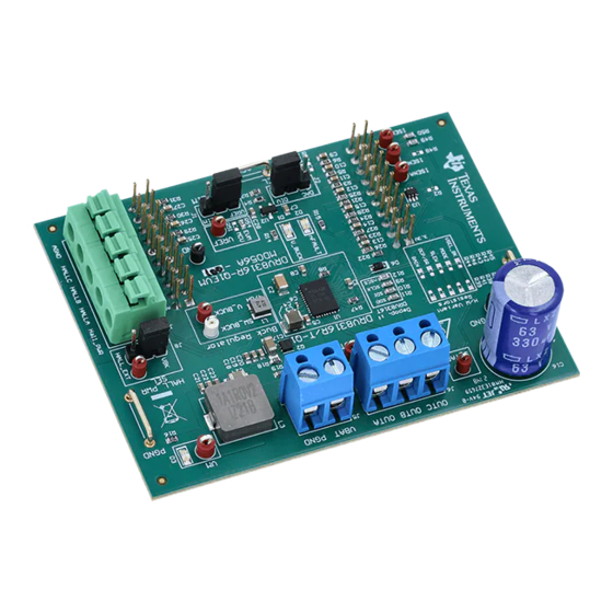
LAUNCHXL-F280049C + DRV8316xEVM, installing software, and running the project to spin a motor, refer to Section 5 Hardware Setup. Figure 2-1. DRV8316xEVM PCB Layout DRV8316xEVM Evaluation Module SLVUBZ9B – DECEMBER 2020 – REVISED AUGUST 2021 Submit Document Feedback Copyright © 2021 Texas Instruments Incorporated... -
Page 5: Quick Start Guide
5. Connect a Micro-USB cable from the computer into the Micro USB connector on the top of the LAUNCHXL- F280049C. SLVUBZ9B – DECEMBER 2020 – REVISED AUGUST 2021 DRV8316xEVM Evaluation Module Submit Document Feedback Copyright © 2021 Texas Instruments Incorporated... -
Page 6: Hardware And Software Overview
Lights up when fault condition has occurred on DRV8316 Green Power is supplied to the board MCU_LED Orange MCU debugging DRV8316xEVM Evaluation Module SLVUBZ9B – DECEMBER 2020 – REVISED AUGUST 2021 Submit Document Feedback Copyright © 2021 Texas Instruments Incorporated... -
Page 7: Figure 4-1. Drv8316Xevm Leds
Hardware and Software Overview VM LED 3.3VBK LED nFAULTLED MCU LED Figure 4-1. DRV8316xEVM LEDs SLVUBZ9B – DECEMBER 2020 – REVISED AUGUST 2021 DRV8316xEVM Evaluation Module Submit Document Feedback Copyright © 2021 Texas Instruments Incorporated... -
Page 8: Table 4-2. Description Of User Selectable Settings On Drv8316Xevm
Center tap voltage of motor voltage of motor (R52 must be are populated can be measured through populated) C_TAP test point DRV8316xEVM Evaluation Module SLVUBZ9B – DECEMBER 2020 – REVISED AUGUST 2021 Submit Document Feedback Copyright © 2021 Texas Instruments Incorporated... -
Page 9: Figure 4-2. User-Selectable Jumpers And Dnp Components On Top Side Of Drv8316Xevm
(B) J1 = VREF/ILIM select (C) J2 = ILIM select CSA outputs Figure 4-2. User-Selectable Jumpers and DNP Components on Top Side of DRV8316xEVM SLVUBZ9B – DECEMBER 2020 – REVISED AUGUST 2021 DRV8316xEVM Evaluation Module Submit Document Feedback Copyright © 2021 Texas Instruments Incorporated... -
Page 10: Figure 4-3. User-Selectable Jumpers And Dnp Components On Bottom Side Drv8316Xevm
Table 4-3. Status of Resistors for DRV8316R and DRV8316T Variants (defaults in bold) Device Variant R9-R12 Status R37-R46 Status DRV8316R Populated DRV8316T Hardware User adjustable DRV8316xEVM Evaluation Module SLVUBZ9B – DECEMBER 2020 – REVISED AUGUST 2021 Submit Document Feedback Copyright © 2021 Texas Instruments Incorporated... -
Page 11: Figure 4-4. Resistor Divider Settings (R37-R46) And Resistors To Disable Spi (R9-R12)
(10-90%) and high to low Hi-Z 50 V/µs (90-10%) 47 kΩ to AVDD 125 V/µs Tied to AVDD 200 V/µs SLVUBZ9B – DECEMBER 2020 – REVISED AUGUST 2021 DRV8316xEVM Evaluation Module Submit Document Feedback Copyright © 2021 Texas Instruments Incorporated... -
Page 12: Hardware Connections Overview - Drv8316Xevm + Launchxl-F280049C
8-A peak current and can be used in systems implementing sensored, sensorless, or field-oriented control. The 3.3-V supply to the Hall sensors is derived by the buck converter integrated in the DRV8316. DRV8316xEVM Evaluation Module SLVUBZ9B – DECEMBER 2020 – REVISED AUGUST 2021 Submit Document Feedback Copyright © 2021 Texas Instruments Incorporated... -
Page 13: Connection Details
To connect Hall sensor outputs to the Hall connector on the DRV8316xEVM, push down on the respective terminals to open the sockets and insert the Hall sensor connections. SLVUBZ9B – DECEMBER 2020 – REVISED AUGUST 2021 DRV8316xEVM Evaluation Module Submit Document Feedback Copyright © 2021 Texas Instruments Incorporated... -
Page 14: Figure 4-6. Connections From Motor To Drv8316Xevm
LaunchPad firmware and GUI as well as the correct installment of the DRV8316xEVM to the J1/J3 and J2/J4 headers of the LaunchPad. DRV8316xEVM Evaluation Module SLVUBZ9B – DECEMBER 2020 – REVISED AUGUST 2021 Submit Document Feedback Copyright © 2021 Texas Instruments Incorporated... -
Page 15: Figure 4-7. Drv8316Xevm On Headers J1/J3 And J2/J4 Of Launchpad
Hardware and Software Overview Micro- USB Figure 4-7. DRV8316xEVM on Headers J1/J3 and J2/J4 of LaunchPad ™ and Micro-USB Plugged Into LaunchPad ™ SLVUBZ9B – DECEMBER 2020 – REVISED AUGUST 2021 DRV8316xEVM Evaluation Module Submit Document Feedback Copyright © 2021 Texas Instruments Incorporated... -
Page 16: Interfacing Drv8316Xevm And Launchxl-F280049C Launchpad
PWM used to switch Phase C high- side FET Not used XRSn Not used INLC GPIO5/PWM3B PWM used to switch Phase C low- side FET DRV8316xEVM Evaluation Module SLVUBZ9B – DECEMBER 2020 – REVISED AUGUST 2021 Submit Document Feedback Copyright © 2021 Texas Instruments Incorporated... - Page 17 Not used GPIO23/LED4 LED reserved on LaunchPad VREF (DNP) GPIO25 For internal use only MCU_LED GPIO59 Visual feedback for LaunchPad connection SLVUBZ9B – DECEMBER 2020 – REVISED AUGUST 2021 DRV8316xEVM Evaluation Module Submit Document Feedback Copyright © 2021 Texas Instruments Incorporated...
-
Page 18: Hardware Setup
Figure 5-1 shows. Figure 5-1. Bottom Silk Screen Shows Names of Pins When Using an External MCU DRV8316xEVM Evaluation Module SLVUBZ9B – DECEMBER 2020 – REVISED AUGUST 2021 Submit Document Feedback Copyright © 2021 Texas Instruments Incorporated... -
Page 19: Firmware And Gui Application
Brushless-DC motor. The supported firmware is a sensorless ield-oriented control algorithm adapted from Texas Instruments’ MotorControl SDK Library of motor solutions. The algorithm includes motor identification and parameters, sensorless sinusoidal commutation, torque and speed control, and field weakening to maximize the performance of the motor. -
Page 20: Motor Identification
Rs, Rs Online, Ls-d, Ls-q, Flux, and Rr will update for that motor as shown in Figure 6-3. These values will be automatically used for sensorless Field-oriented control. DRV8316xEVM Evaluation Module SLVUBZ9B – DECEMBER 2020 – REVISED AUGUST 2021 Submit Document Feedback Copyright © 2021 Texas Instruments Incorporated... -
Page 21: Figure 6-3. Motor Identification Using The Drv8316Xevm Instaspin ™ Gui
Firmware and GUI Application Figure 6-3. Motor Identification Using the DRV8316xEVM InstaSPIN ™ SLVUBZ9B – DECEMBER 2020 – REVISED AUGUST 2021 DRV8316xEVM Evaluation Module Submit Document Feedback Copyright © 2021 Texas Instruments Incorporated... -
Page 22: Sensorless-Foc Commutation
GUI, the user must build and compile the project in CCS, and import the .out binary file for that project into the GUI properties through Composer. More information can be found in the README when the GUI is first opened. DRV8316xEVM Evaluation Module SLVUBZ9B – DECEMBER 2020 – REVISED AUGUST 2021 Submit Document Feedback Copyright © 2021 Texas Instruments Incorporated... -
Page 23: Spi Communication (Drv8316R Only)
Click on the “Manual Write” box to read the data from that address. ™ Figure 6-5. SPI Communication Using the DRV8316xEVM InstaSPIN SLVUBZ9B – DECEMBER 2020 – REVISED AUGUST 2021 DRV8316xEVM Evaluation Module Submit Document Feedback Copyright © 2021 Texas Instruments Incorporated... -
Page 24: Drv8316Xevm Schematics
7 DRV8316xEVM Schematics Figure 7-1. Main Supply, Reverse Polarity Protection, and Pi Filter Schematic Figure 7-2. Voltage Sense and Protection Schematic DRV8316xEVM Evaluation Module SLVUBZ9B – DECEMBER 2020 – REVISED AUGUST 2021 Submit Document Feedback Copyright © 2021 Texas Instruments Incorporated... -
Page 25: Figure 7-3. Connectors And Interface Schematic
DRV8316xEVM Schematics Figure 7-3. Connectors and Interface Schematic Figure 7-4. DRV8316 3-phase BLDC Motor Driver Schematic SLVUBZ9B – DECEMBER 2020 – REVISED AUGUST 2021 DRV8316xEVM Evaluation Module Submit Document Feedback Copyright © 2021 Texas Instruments Incorporated... -
Page 26: Figure 7-5. Vref / Ilim Schematic
Figure 7-5. VREF / ILIM Schematic Figure 7-6. 3.3V Integrated Buck Regulator Schematic Figure 7-7. TMS430F280049C LaunchPad Connections Schematic DRV8316xEVM Evaluation Module SLVUBZ9B – DECEMBER 2020 – REVISED AUGUST 2021 Submit Document Feedback Copyright © 2021 Texas Instruments Incorporated... -
Page 27: Revision History
Changes from Revision * (December 2020) to Revision A (February 2021) Page • Added Cautions and Warnings section.......................3 • Changed instructions in the C2000™ InstaSPIN™ Universal GUI section............SLVUBZ9B – DECEMBER 2020 – REVISED AUGUST 2021 DRV8316xEVM Evaluation Module Submit Document Feedback Copyright © 2021 Texas Instruments Incorporated... - Page 28 TI products. TI’s provision of these resources does not expand or otherwise alter TI’s applicable warranties or warranty disclaimers for TI products.IMPORTANT NOTICE Mailing Address: Texas Instruments, Post Office Box 655303, Dallas, Texas 75265 Copyright © 2021, Texas Instruments Incorporated...
Need help?
Do you have a question about the DRV8316 EVM Series and is the answer not in the manual?
Questions and answers