Table of Contents
Advertisement
Quick Links
Advertisement
Table of Contents

Related Manuals for Texas Instruments DRA7 Series


Summary of Contents for Texas Instruments DRA7 Series
- Page 1 DRA7x EVM CPU Board User's Guide Literature Number: SPRUI50 February 2016...
-
Page 2: Table Of Contents
....................... Power Monitoring ................CPU Board With Components Identification ..................USB3 Supported Configurations ........................Option 1 ........................Option 2 ........................Option 3 ........................References Table of Contents SPRUI50 – February 2016 Submit Documentation Feedback Copyright © 2016, Texas Instruments Incorporated... - Page 3 ............ Qualtek 3023007-01M USB3.0 Micro-AB to Micro-B 1m (3.28') .................. IOGEAR GUH374 4-Port USB3.0 Hub ..........Qualtek 3023005-01M USB3.0 Standard-A to Micro-B 1m (3.28') SPRUI50 – February 2016 List of Figures Submit Documentation Feedback Copyright © 2016, Texas Instruments Incorporated...
- Page 4 ..................I2C3 vs DCAN2 Selection Table ....................I2C Device Address Chart ....................GPIO Expander IO Chart ................Configuration EEPROM Definition Table ........................GPIO List List of Tables SPRUI50 – February 2016 Submit Documentation Feedback Copyright © 2016, Texas Instruments Incorporated...
-
Page 5: Introduction
Soldered-down processor used for high performance Use Cases and evaluations All other components on-board are soldered-down. OMAP is a trademark of Texas Instruments. ARM, Cortex are registered trademarks of ARM Limited. POWERVR is a registered trademark of Imagination Technologies Limited. -
Page 6: Evm System Configurations
Daughter Bd, Power Supply and Limited Accessory Cables. ES1.0 EVM Vision Kit Socketed CPU Board, Vision Apps Bd, LCD/TS EVM5777X-01-40-00 Daughter Bd, Power Supply and Limited Accessory Cables. DRA7x EVM CPU Board SPRUI50 – February 2016 Submit Documentation Feedback Copyright © 2016, Texas Instruments Incorporated... -
Page 7: Production Boards (Obsolete)
Limited Accessory Cables. ES2.0 GP EVM Vision Kit CPU Board, Vision Apps Bd, 10.1” LCD/TS Daughter Bd EVM5777G-03-40-00 and Limited Accessory Cables. SPRUI50 – February 2016 DRA7x EVM CPU Board Submit Documentation Feedback Copyright © 2016, Texas Instruments Incorporated... -
Page 8: Cpu Board Feature List
– 14-pin adapter: 7 x 2, 2.54mm pitch • Audio input and output: – AIC3106 codec: Headphone OUT, Line OUT, Line IN, Microphone IN DRA7x EVM CPU Board SPRUI50 – February 2016 Submit Documentation Feedback Copyright © 2016, Texas Instruments Incorporated... - Page 9 – Support sleep mode with wake-up capability • PCB: – Dimension (W x D): 170mm x 170mm – Expansion Connectors to support application boards SPRUI50 – February 2016 DRA7x EVM CPU Board Submit Documentation Feedback Copyright © 2016, Texas Instruments Incorporated...
-
Page 10: Hardware
The CPU board has two push buttons for reset: • Power ON reset (PORz) (or cold reset for complete system reset) • Warm reset (RESETn) DRA7x EVM CPU Board SPRUI50 – February 2016 Submit Documentation Feedback Copyright © 2016, Texas Instruments Incorporated... -
Page 11: Reset Structure
NOTE: ES1.0 Rev E system and older supported an on-board pushbutton to generate wakeup event. Depending on revision, the button was connected to either Wakeup1 or Wakeup2. SPRUI50 – February 2016 DRA7x EVM CPU Board Submit Documentation Feedback Copyright © 2016, Texas Instruments Incorporated... -
Page 12: Boot Modes
“ON” position, corresponding to a “Low” logic level signal. Alternatively, when switch is in the “OFF” position, a 10k pull-up connects it to 3.3 V rail, corresponding to a “High” logic level signal. DRA7x EVM CPU Board SPRUI50 – February 2016 Submit Documentation Feedback Copyright © 2016, Texas Instruments Incorporated... -
Page 13: Board Controls For Booting Options
(SW8.2 reused in Rev G+, display support) boards for AIC I2C address OFF = Low = I2C=0X18 (for AIC operation with 7” selection) display support) SPRUI50 – February 2016 DRA7x EVM CPU Board Submit Documentation Feedback Copyright © 2016, Texas Instruments Incorporated... -
Page 14: Cpu Board Switch And Button Locations (Rev E And Earlier)
Hardware www.ti.com Figure 4. CPU Board Switch and Button Locations (Rev E and earlier) DRA7x EVM CPU Board SPRUI50 – February 2016 Submit Documentation Feedback Copyright © 2016, Texas Instruments Incorporated... -
Page 15: Signal Multiplex Logic
The following sections and diagrams illustrate the flexibility of the on-die and CPU’s on-board signal multiplexing options. SPRUI50 – February 2016 DRA7x EVM CPU Board Submit Documentation Feedback Copyright © 2016, Texas Instruments Incorporated... -
Page 16: Nor/Nand Booting Vs Fpd-Link Video Multiplexing
The “resistor muxing” option would need to change to route the GPMC signals via “Bus Logic Switch Path” to the NOR Flash memory in order to access the full addressable range of the NOR memory. DRA7x EVM CPU Board SPRUI50 – February 2016 Submit Documentation Feedback Copyright © 2016, Texas Instruments Incorporated... -
Page 17: Qspi Vs Full Address Nor Flash Multiplexing
The default interface are the GPMC signals; the selection table is shown in Table Table 14. GPMC and MMC2 Selection Table GPMC vs MMC2 MMC2_BOOT Interface Device GPMC/MMC2 GPMC NOR Flash MMC2 eMMC SPRUI50 – February 2016 DRA7x EVM CPU Board Submit Documentation Feedback Copyright © 2016, Texas Instruments Incorporated... -
Page 18: Vin1A And Li Camera Multiplexing
Use Bit “P3” in the I2C IO Expander(U119) with slave address 0x0100 0100(Write) to control, signal "CAM_FPD_MUX_S0". 3.4.5 VIN2A Vs RGMII1 Multiplex control logic for VIN2A and RGMII1 is shown in Figure Figure 10. VIN2A and RGMII1 Multiplexing DRA7x EVM CPU Board SPRUI50 – February 2016 Submit Documentation Feedback Copyright © 2016, Texas Instruments Incorporated... -
Page 19: Vin5A And Mlb Multiplexing
0R538, R526, R525 MLB Interface MLB Conn 3.4.7 VIN4B vs RGMII0 Multiplex control logic for VIN4B and RGMII0. Figure 12. VIN4B and RGMII0 Multiplexing SPRUI50 – February 2016 DRA7x EVM CPU Board Submit Documentation Feedback Copyright © 2016, Texas Instruments Incorporated... -
Page 20: Vin6A And Mcasp1, 2, 3 And 7 Multiplexing
Use Bit “P1” in I2C IO Expander (U119) with slave address 0x0100 0100(Write) to control, signal "VIN6_SEL_S0". 3.4.9 UART3 Vs SPI[2] Multiplex control logic for UART3 and SPI[2]. Figure 14. UART3 and SPI[2] Multiplexing DRA7x EVM CPU Board SPRUI50 – February 2016 Submit Documentation Feedback Copyright © 2016, Texas Instruments Incorporated... -
Page 21: Uart1 Vs Uart3 Multiplexing
"UART_SEL1_3". A DIP switch is also available to control the UART_SEL1_3 signal for boot mode configuration. 3.4.11 I2C2 Vs HDMI Multiplex control logic for I2C2 and HDMI. Figure 16. I2C2 Vs HDMI Multiplexing SPRUI50 – February 2016 DRA7x EVM CPU Board Submit Documentation Feedback Copyright © 2016, Texas Instruments Incorporated... -
Page 22: I2C Interface
Either U117 or U109 will be mounted on board GPIO Expander PCF8575 0x20 GPIO Expander PCF8575 0x21 MLB Connector Connector LCD Interface Connector DRA7x EVM CPU Board SPRUI50 – February 2016 Submit Documentation Feedback Copyright © 2016, Texas Instruments Incorporated... -
Page 23: Gpio Expander Io Chart
USB2 Over Current Indication PCI_SW_RESETn PCI Interface SW Reset CON_LCD_PWR_DN LCD Board Master power enable No Connection TMP102_ALERT Digital Temp. sensor Altert signal SPRUI50 – February 2016 DRA7x EVM CPU Board Submit Documentation Feedback Copyright © 2016, Texas Instruments Incorporated... - Page 24 COM8 interface level shifter enable signal SEL_UART3_SPI2 MUX out control signal for UART3 Vs SPI2 FORCE_EMU MUX out control signal for EMU signals DRA7x EVM CPU Board SPRUI50 – February 2016 Submit Documentation Feedback Copyright © 2016, Texas Instruments Incorporated...
- Page 25 MMC2_BOOT_OVR MMC2 DIP Switch Override (Rev NOR_BOOT_OVR_OEN NOR BOOT DIP Switch Override Enable (Rev G) NOR_BOOT_OVR NOR BOOT DIP Switch Override (Rev G) SPRUI50 – February 2016 DRA7x EVM CPU Board Submit Documentation Feedback Copyright © 2016, Texas Instruments Incorporated...
-
Page 26: Configuration Eeprom Definition Table
Char board_name[16]; Unsigned short version_major; Unsigned short version_minor; Unsigned long config_option; Unsigned long emif1_size_bytes; Unsigned long emif2_size_bytes; Char reserved[28]; } eeprom_id; 56 Bytes DRA7x EVM CPU Board SPRUI50 – February 2016 Submit Documentation Feedback Copyright © 2016, Texas Instruments Incorporated... -
Page 27: Gpio List
RGMII0_TXD0 (EXP_P1.35) GPIO5_25 (U6) Application Board Expansion Connector GP5[22] C_EMAC[0]_TXD3 RGMII0_TXD3 (EXP_P1.33) GPIO5_22 (V7) Application Board Expansion Connector GP2[27] GPMC_BEN1 (EXP_P2.108) GPIO2_27 (M4) SPRUI50 – February 2016 DRA7x EVM CPU Board Submit Documentation Feedback Copyright © 2016, Texas Instruments Incorporated... -
Page 28: Tag And Emulator
CPU board. For power on/off sequence, see TPS65903x-Q1 Automotive Power Management Unit (PMU) for Processor Data Sheet (SWCS095). DRA7x EVM CPU Board SPRUI50 – February 2016 Submit Documentation Feedback Copyright © 2016, Texas Instruments Incorporated... -
Page 29: Power Monitoring
I2C bus. This allows the device to be placed close to the shunt. SPRUI50 – February 2016 DRA7x EVM CPU Board Submit Documentation Feedback Copyright © 2016, Texas Instruments Incorporated... -
Page 30: Power Monitoring Block Diagram
VDD_MPU • VDD_GPU • VDD_DSPEVE • CORE_VDD • VDD_IVA • CPU_VDD_DDR • VDD_DDR • VDDS18V • VDDA_1V8_PLL • VDDA_1V8_PHY • VUSB_3V3 • VDDSHV DRA7x EVM CPU Board SPRUI50 – February 2016 Submit Documentation Feedback Copyright © 2016, Texas Instruments Incorporated... -
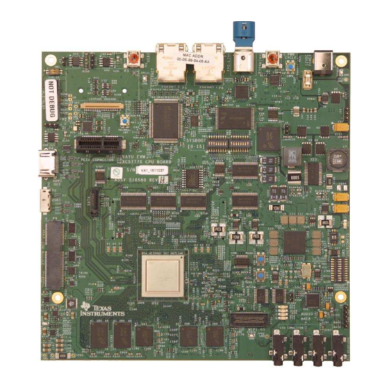
Page 31: Cpu Board With Components Identification
– Host connects to the EVM acting as a device • Standard-A plug to Micro-B plug – Host connects to the EVM acting as a device SPRUI50 – February 2016 DRA7x EVM CPU Board Submit Documentation Feedback Copyright © 2016, Texas Instruments Incorporated... -
Page 32: Option 1
Side HUB Side Figure 21. 3023009-01M USB 3.0 Micro-AB TO Standard-B 1m (3.28’) Figure 22. Qualtek SIIG JU-H40312-S14Pport USB3.0 Super Speed USB Hub DRA7x EVM CPU Board SPRUI50 – February 2016 Submit Documentation Feedback Copyright © 2016, Texas Instruments Incorporated... -
Page 33: Option 2
Figure uEVM5432 Side USB3.0 HUB Side Figure 23. Qualtek 3023007-01M USB3.0 Micro-AB to Micro-B 1m (3.28') Figure 24. IOGEAR GUH374 4-Port USB3.0 Hub SPRUI50 – February 2016 DRA7x EVM CPU Board Submit Documentation Feedback Copyright © 2016, Texas Instruments Incorporated... -
Page 34: Option 3
• CPU EVM BOM Rev H (SPRR211) • CPU EVM Assembly Drawing Rev H (SPRR212) • CPU EVM PCB Drawing Rev H (SPRR213) DRA7x EVM CPU Board SPRUI50 – February 2016 Submit Documentation Feedback Copyright © 2016, Texas Instruments Incorporated... - Page 35 STANDARD TERMS AND CONDITIONS FOR EVALUATION MODULES Delivery: TI delivers TI evaluation boards, kits, or modules, including any accompanying demonstration software, components, or documentation (collectively, an “EVM” or “EVMs”) to the User (“User”) in accordance with the terms and conditions set forth herein. Acceptance of the EVM is expressly subject to the following terms and conditions.
- Page 36 FCC Interference Statement for Class B EVM devices NOTE: This equipment has been tested and found to comply with the limits for a Class B digital device, pursuant to part 15 of the FCC Rules. These limits are designed to provide reasonable protection against harmful interference in a residential installation.
- Page 37 【無線電波を送信する製品の開発キットをお使いになる際の注意事項】 開発キットの中には技術基準適合証明を受けて いないものがあります。 技術適合証明を受けていないもののご使用に際しては、電波法遵守のため、以下のいずれかの 措置を取っていただく必要がありますのでご注意ください。 1. 電波法施行規則第6条第1項第1号に基づく平成18年3月28日総務省告示第173号で定められた電波暗室等の試験設備でご使用 いただく。 2. 実験局の免許を取得後ご使用いただく。 3. 技術基準適合証明を取得後ご使用いただく。 なお、本製品は、上記の「ご使用にあたっての注意」を譲渡先、移転先に通知しない限り、譲渡、移転できないものとします。 上記を遵守頂けない場合は、電波法の罰則が適用される可能性があることをご留意ください。 日本テキサス・イ ンスツルメンツ株式会社 東京都新宿区西新宿6丁目24番1号 西新宿三井ビル 3.3.3 Notice for EVMs for Power Line Communication: Please see http://www.tij.co.jp/lsds/ti_ja/general/eStore/notice_02.page 電力線搬送波通信についての開発キットをお使いになる際の注意事項については、次のところをご覧くださ い。http://www.tij.co.jp/lsds/ti_ja/general/eStore/notice_02.page SPACER EVM Use Restrictions and Warnings: 4.1 EVMS ARE NOT FOR USE IN FUNCTIONAL SAFETY AND/OR SAFETY CRITICAL EVALUATIONS, INCLUDING BUT NOT LIMITED TO EVALUATIONS OF LIFE SUPPORT APPLICATIONS.
- Page 38 Notwithstanding the foregoing, any judgment may be enforced in any United States or foreign court, and TI may seek injunctive relief in any United States or foreign court. Mailing Address: Texas Instruments, Post Office Box 655303, Dallas, Texas 75265 Copyright © 2015, Texas Instruments Incorporated...
- Page 39 IMPORTANT NOTICE Texas Instruments Incorporated and its subsidiaries (TI) reserve the right to make corrections, enhancements, improvements and other changes to its semiconductor products and services per JESD46, latest issue, and to discontinue any product or service per JESD48, latest issue.
Need help?
Do you have a question about the DRA7 Series and is the answer not in the manual?
Questions and answers