Advertisement
Quick Links
This user's guide is intended for software and hardware engineers developing applications for the Jacinto
6 high performance, multimedia application processor based on enhanced OMAP™ architecture
implemented with 28-nm technology. It describes the evaluation module (EVM) CPU board's hardware,
firmware and software functions supplied by Texas Instruments Inc.
...................................................................................................................
1
Introduction
......................................................................................................................
2
Overview
......................................................................................................................
3
Hardware
4
Signal Multiplex Logic
5
Application Boards
6
USB3 Supported Configurations
..................................................................................................................
7
References
...................................................................................................................
1
CPU Board
2
CPU Board - Front
3
CPU Board - Back
4
CPU Board Block Diagram
5
Power Distribution Block Diagram
6
Reset Structure
7
Mux Diagram for GPMC/QSPI
8
Mux Diagram for GPMC/VOUT3
9
Mux Diagram for GPMC/EMMC
10
Mux Diagram for VIN2A
11
Mux Diagram for VIN2A/RGMII1
12
Mux Diagram for McASP3/7
13
Mux Diagram for RGMII0/VIN1B
14
Mux Diagram for SPI2/UART3
15
Mux Diagram for DCAN2/I2C
16
Mux Diagram for I2C/DDC
17
RGB-to-HDMI Application Bd
1
SoC EVMs/Kits
2
EVM Accessories
3
EVM Kit Truth Table
4
Compatible Wall Supplies (12 V, 5A, 65W)
5
Reset Signals Structure
6
SoC Boot Mode Switch Settings
7
Board Controls for Booting Options
...................................................................................................................
8
User LEDs
9
User Switches
SPRUII5A – December 2017 – Revised November 2018
Submit Documentation Feedback
DRA77xP/DRA76xP-ACD CPU EVM Board
......................................................................................................
.........................................................................................................
.........................................................................................
...........................................................................................................
...........................................................................................................
.................................................................................................
.........................................................................................
.............................................................................................................
............................................................................................
.........................................................................................
..........................................................................................
...................................................................................................
.........................................................................................
..............................................................................................
.........................................................................................
...........................................................................................
.............................................................................................
................................................................................................
.............................................................................................
...............................................................................................................
............................................................................................................
.........................................................................................................
.............................................................................
...................................................................................................
.........................................................................................
......................................................................................
..............................................................................................................
Copyright © 2017–2018, Texas Instruments Incorporated
SPRUII5A – December 2017 – Revised November 2018
Contents
List of Figures
List of Tables
DRA77xP/DRA76xP-ACD CPU EVM Board
User's Guide
2
2
8
23
33
34
37
3
6
7
8
9
10
24
26
26
27
28
29
30
31
32
33
34
4
4
4
10
11
13
13
17
17
1
Advertisement

Related Manuals for Texas Instruments DRA77xP-ACD


Summary of Contents for Texas Instruments DRA77xP-ACD
- Page 1 This user's guide is intended for software and hardware engineers developing applications for the Jacinto 6 high performance, multimedia application processor based on enhanced OMAP™ architecture implemented with 28-nm technology. It describes the evaluation module (EVM) CPU board’s hardware, firmware and software functions supplied by Texas Instruments Inc. Contents ........................
- Page 2 SoC Pinmux for DCAN2 ....................SoC Pinmux for I2C/HDMI Trademarks OMAP is a trademark of Texas Instruments. Arm, Cortex are registered trademarks of ARM Limited. POWERVR is a trademark of Imagination Technologies Limited. Introduction The DRA77xP/DRA76xP-ACD is an evaluation platform designed To allow scalability and re-use across DRA77xP and DRA76xP “Jacinto”...
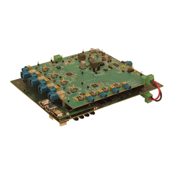
- Page 3 Soldered-down processor used for high performance Use Cases and evaluations All other components on-board are soldered-down. Figure 1. CPU Board SPRUII5A – December 2017 – Revised November 2018 DRA77xP/DRA76xP-ACD CPU EVM Board Submit Documentation Feedback Copyright © 2017–2018, Texas Instruments Incorporated...
- Page 4 Rev A (CPU Bd) DRA76xP/DRA77xP /TDA2Px-ACD ES1.0 GP EVM Infotainment Kit Rev DRA76xP/DRA77xP /TDA2Px-ACD ES1.0 GP EVM Kit Rev A DRA77xP/DRA76xP-ACD CPU EVM Board SPRUII5A – December 2017 – Revised November 2018 Submit Documentation Feedback Copyright © 2017–2018, Texas Instruments Incorporated...
- Page 5 – Universal Asynchronous Receiver/Transmitter (UART) terminal via USB FTDI converter (mini-A/B USB) – COM8Q module interface for Bluetooth and WLAN support SPRUII5A – December 2017 – Revised November 2018 DRA77xP/DRA76xP-ACD CPU EVM Board Submit Documentation Feedback Copyright © 2017–2018, Texas Instruments Incorporated...
- Page 6 MIPI-60 JTAG Power Camera Measurement DDR3L Memory CAN/CAN-FD Fusion Lout Connector Codec Audio (12VDC) Figure 2. CPU Board - Front DRA77xP/DRA76xP-ACD CPU EVM Board SPRUII5A – December 2017 – Revised November 2018 Submit Documentation Feedback Copyright © 2017–2018, Texas Instruments Incorporated...
- Page 7 Only) USB 2.0 HDMI DDR3L CSI2 Memory Touch Expansion Panel RGB2HDMI Expansion Board Figure 3. CPU Board - Back SPRUII5A – December 2017 – Revised November 2018 DRA77xP/DRA76xP-ACD CPU EVM Board Submit Documentation Feedback Copyright © 2017–2018, Texas Instruments Incorporated...
- Page 8 A[27:19], CS[1] Power SD/MMC 60-pin MIPI JTAG Socket Copyright © 2017, Texas Instruments Incorporated Figure 4. CPU Board Block Diagram DRA77xP/DRA76xP-ACD CPU EVM Board SPRUII5A – December 2017 – Revised November 2018 Submit Documentation Feedback Copyright © 2017–2018, Texas Instruments Incorporated...
- Page 9 A sink/source regulator provides the DDR power and termination rails. Copyright © 2017, Texas Instruments Incorporated Copyright © 2017, Texas Instruments Incorporated Figure 5. Power Distribution Block Diagram An external power supply is required to power the EVM, but is not included as part of the EVM kit. The external power supply requirements are: Power Jack: 2.5 mm ID, 5.5 mm OD...
- Page 10 (Cold Reset) PMIC_RESET_OUT PMIC_RESET_IN RTC_PORZ PMIC PMIC_RESWARMN RSTOUT System RSTOUTn Copyright © 2017, Texas Instruments Incorporated Figure 6. Reset Structure DRA77xP/DRA76xP-ACD CPU EVM Board SPRUII5A – December 2017 – Revised November 2018 Submit Documentation Feedback Copyright © 2017–2018, Texas Instruments Incorporated...
- Page 11 QSPI flash is enabled by default. Ensure the correct SoC boot mode is set using the SYS_BOOT switches (SW3, SW4). SPRUII5A – December 2017 – Revised November 2018 DRA77xP/DRA76xP-ACD CPU EVM Board Submit Documentation Feedback Copyright © 2017–2018, Texas Instruments Incorporated...
- Page 12 Note that these SoC resources can be “redeployed” to support alternate interfaces after boot-up by way of both SoC pin EVM mux settings. DRA77xP/DRA76xP-ACD CPU EVM Board SPRUII5A – December 2017 – Revised November 2018 Submit Documentation Feedback Copyright © 2017–2018, Texas Instruments Incorporated...
- Page 13 Failure to adhere to this requirement will cause NOR & NAND memory data bus contention. 2. UART3 peripheral boot and terminal access requires a on-board resistor modification. SPRUII5A – December 2017 – Revised November 2018 DRA77xP/DRA76xP-ACD CPU EVM Board Submit Documentation Feedback Copyright © 2017–2018, Texas Instruments Incorporated...
- Page 14 3.11 Wired Ethernet Dual Gigabit Ethernet ports are supported on the EVM. RGMII ports 0 and 1 drive the Texas Instruments DP83867 Gigabit PHYs. The PHYs are configured through the Management Data Input/Output (MDIO) bus, with the address set to 0x2 (port 0) and 0x3 (port 1). PHYs are reset at Power-on, but can also be independently reset using the IO expander.
- Page 15 This is typically needed if the frequency of the clock is above 70 MHz. The de-jitter IC is configured via I2C (port 1, 0x65). • Serializer device used: Texas Instruments DS90UH921Q • Clock de-jitter device used: Texas Instruments CDCE813-Q1 • Connector used: Automotive HSD Connector, right-angle plug for PCB, Rosenberger D4S20D-40ML5- 3.13 Video Input 3.13.1 Parallel Imaging Parallel video input is supported through connections from external sensors and transceivers.
- Page 16 (default is OFF) and IO expander (EXP2, P17) must be low by software (default is high). NOTE: The use of this feature is recommended only for specific users. DRA77xP/DRA76xP-ACD CPU EVM Board SPRUII5A – December 2017 – Revised November 2018 Submit Documentation Feedback Copyright © 2017–2018, Texas Instruments Incorporated...
- Page 17 CPU IO power rail for VDDSHV8 0x4B VDDA_USB3V3 10m-Ω CPU USB3v3 power rail 0x4C VDA_PLL_1V8 10m-Ω CPU PLL Power Rail SPRUII5A – December 2017 – Revised November 2018 DRA77xP/DRA76xP-ACD CPU EVM Board Submit Documentation Feedback Copyright © 2017–2018, Texas Instruments Incorporated...
- Page 18 PMIC TPS917 0x58-5B, 0x12 LP87565 0x60 FPD-Link Clock CDC813-Q1 0x65 MLB Connector Connector COM8 Connector Connector LCD Interface Connector DRA77xP/DRA76xP-ACD CPU EVM Board SPRUII5A – December 2017 – Revised November 2018 Submit Documentation Feedback Copyright © 2017–2018, Texas Instruments Incorporated...
- Page 19 Micro-SD Connector H_MMC_PWR_ON Card Power Enable GPIO4_21 NOTE: Functional signals of pin mux are not considered for this table. SPRUII5A – December 2017 – Revised November 2018 DRA77xP/DRA76xP-ACD CPU EVM Board Submit Documentation Feedback Copyright © 2017–2018, Texas Instruments Incorporated...
- Page 20 NOR boot Chip select enable signal MMC2_BOOT MUX out control signal for GPMC Vs MMC2 TMP102_ALERT Temperature sensor alert indicator DRA77xP/DRA76xP-ACD CPU EVM Board SPRUII5A – December 2017 – Revised November 2018 Submit Documentation Feedback Copyright © 2017–2018, Texas Instruments Incorporated...
- Page 21 Override Enable MMC2_BOOT_OVR MMC2 DIP Switch Override NOR_BOOT_OVR_O NOR BOOT DIP Switch Override Enable NOR_BOOT_OVR NOR BOOT DIP Switch Override SPRUII5A – December 2017 – Revised November 2018 DRA77xP/DRA76xP-ACD CPU EVM Board Submit Documentation Feedback Copyright © 2017–2018, Texas Instruments Incorporated...
- Page 22 Unsigned short version_major; Unsigned short version_minor; Unsigned long config_option; Unsigned long emif1_size_bytes; Unsigned long emif2_size_bytes; Char reserved[28]; } eeprom_id; DRA77xP/DRA76xP-ACD CPU EVM Board SPRUII5A – December 2017 – Revised November 2018 Submit Documentation Feedback Copyright © 2017–2018, Texas Instruments Incorporated...
- Page 23 RGMII0 to Gig PHY (default) SW6.[3] GPMC to NOR (RU5) MMC2 to eMMC EXP3.P[15:14] '00' eMMC Memory '11' Memory selected by SW6.3 SPRUII5A – December 2017 – Revised November 2018 DRA77xP/DRA76xP-ACD CPU EVM Board Submit Documentation Feedback Copyright © 2017–2018, Texas Instruments Incorporated...
- Page 24 QSPI Memory GPMC_A[18:13]._CS[2] GPMC GPMC_A[18:13],_CS[2] NOR Memory Copyright © 2017, Texas Instruments Incorporated Figure 7. Mux Diagram for GPMC/QSPI DRA77xP/DRA76xP-ACD CPU EVM Board SPRUII5A – December 2017 – Revised November 2018 Submit Documentation Feedback Copyright © 2017–2018, Texas Instruments Incorporated...
- Page 25 If booting from NOR/NAND memories, the selection for chip select 0 is made using switch SW6 position 1 (NOR) and position 2 (NAND). NOTE: Only one of these boot devices can be enabled at any time SPRUII5A – December 2017 – Revised November 2018 DRA77xP/DRA76xP-ACD CPU EVM Board Submit Documentation Feedback Copyright © 2017–2018, Texas Instruments Incorporated...
- Page 26 _A[12:0],_CS[3] _DE, _D[23:0], GPIO2_2 FPD-Link Panel Copyright © 2017, Texas Instruments Incorporated Figure 8. Mux Diagram for GPMC/VOUT3 GPMC/EMMC Selection (Mux C) Table 18 shows part of the SoC pinmux table for GPMC. The SoC device supports additional functions not shown in the table.
- Page 27 Connector VIN2A VIN2A_CLK, _VS, _HS, _DE, _D[11:0] LI Camera Connector Copyright © 2017, Texas Instruments Incorporated Figure 10. Mux Diagram for VIN2A SPRUII5A – December 2017 – Revised November 2018 DRA77xP/DRA76xP-ACD CPU EVM Board Submit Documentation Feedback Copyright © 2017–2018, Texas Instruments Incorporated...
- Page 28 Expansion Connector VIN2A VIN2A_D[23:12] LI Camera Connector Copyright © 2017, Texas Instruments Incorporated Figure 11. Mux Diagram for VIN2A/RGMII1 DRA77xP/DRA76xP-ACD CPU EVM Board SPRUII5A – December 2017 – Revised November 2018 Submit Documentation Feedback Copyright © 2017–2018, Texas Instruments Incorporated...
- Page 29 Expansion McASP7_AXR[1:0] McASP3/7 McASP3_ACLKX,_FSX,_AXR[1:0]Mc ASP7_FSX, ACLKX, AXR[1:0] Copyright © 2017, Texas Instruments Incorporated Figure 12. Mux Diagram for McASP3/7 SPRUII5A – December 2017 – Revised November 2018 DRA77xP/DRA76xP-ACD CPU EVM Board Submit Documentation Feedback Copyright © 2017–2018, Texas Instruments Incorporated...
- Page 30 GPIO5[31:29],25,22 Expansion MDIO_MCLK, _D, UART3_TXD, Connector UART3_RXD Copyright © 2017, Texas Instruments Incorporated Figure 13. Mux Diagram for RGMII0/VIN1B DRA77xP/DRA76xP-ACD CPU EVM Board SPRUII5A – December 2017 – Revised November 2018 Submit Documentation Feedback Copyright © 2017–2018, Texas Instruments Incorporated...
- Page 31 Connector SPI2_SCLK, _D[1:0],_CS[0] SPI2 SPI2_SCLK,_D[1:0],_CS[0] Expansion Connector Copyright © 2017, Texas Instruments Incorporated Figure 14. Mux Diagram for SPI2/UART3 SPRUII5A – December 2017 – Revised November 2018 DRA77xP/DRA76xP-ACD CPU EVM Board Submit Documentation Feedback Copyright © 2017–2018, Texas Instruments Incorporated...
- Page 32 Expansion DCAN2 GPIO6_14, GPIO6_15 DCAN2_TX,_RX DCAN2 Connector Copyright © 2017, Texas Instruments Incorporated Figure 15. Mux Diagram for DCAN2/I2C DRA77xP/DRA76xP-ACD CPU EVM Board SPRUII5A – December 2017 – Revised November 2018 Submit Documentation Feedback Copyright © 2017–2018, Texas Instruments Incorporated...
- Page 33 MEASURE I2C2_SCL, _SDA HDMI_DDC_SDA, _SCL HDMI Copyright © 2017, Texas Instruments Incorporated Figure 16. Mux Diagram for I2C/DDC Application Boards The CPU EVM supports several different interfaces for connecting additional boards/EVMs to enhance the feature set of base EVM. The ability to add either existing applications boards to the systems is provided, or you can design your own.
- Page 34 Config I2C3_SCL, _SDA EEPROM TPD12S016 GPIO_PWR_DWN Expander Copyright © 2017, Texas Instruments Incorporated Figure 17. RGB-to-HDMI Application Bd USB3 Supported Configurations The following USB3.x combinations are supportable: • Micro-A plug to Standard-B plug – Connect to hub or external drive/device that has a std B receptacle •...
- Page 35 Use a USB3.0 micro-A to standard-B and USB3.0 Hub as the SIIG one as shown below. uEVM5432 side HUB side SPRUII5A – December 2017 – Revised November 2018 DRA77xP/DRA76xP-ACD CPU EVM Board Submit Documentation Feedback Copyright © 2017–2018, Texas Instruments Incorporated...
- Page 36 Use a USB3.0 micro-A to micro-B and USB3.0 Hub as the IOGEAR one as shown below. uEVM5432 side USB 3.0 HUB Side DRA77xP/DRA76xP-ACD CPU EVM Board SPRUII5A – December 2017 – Revised November 2018 Submit Documentation Feedback Copyright © 2017–2018, Texas Instruments Incorporated...
- Page 37 DRA76xP_DRA77xP_TDA2Px_ACD HDMI DISPLAY ADAPTER Board Assembly Drawing Rev B • DRA76xP_DRA77xP_TDA2Px_ACD HDMI DISPLAY ADAPTER Board PCB Drawing Rev B SPRUII5A – December 2017 – Revised November 2018 DRA77xP/DRA76xP-ACD CPU EVM Board Submit Documentation Feedback Copyright © 2017–2018, Texas Instruments Incorporated...
- Page 38 TI products. TI’s provision of these resources does not expand or otherwise alter TI’s applicable warranties or warranty disclaimers for TI products. Mailing Address: Texas Instruments, Post Office Box 655303, Dallas, Texas 75265 Copyright © 2018, Texas Instruments Incorporated...
Need help?
Do you have a question about the DRA77xP-ACD and is the answer not in the manual?
Questions and answers