
Related Manuals for Ametek BrookField TC Series


Summary of Contents for Ametek BrookField TC Series
- Page 1 TC-Series Circulating Baths with Standard Digital Temperature Controller Operator’s Manual Models: TC-150SD TC-250SD TC-550SD TC-650SD 110-512 BEL/EN 06 September 2018...
-
Page 2: Table Of Contents
Table of Contents Introduction ..............................3 Brookfield Circulating Baths with Standard Digital Temperature Controller ..........3 Performance Specifications ........................4 Heating and Cooling Curves ........................5 General Safety Information ........................7 Safety Recommendations......................... 8 Regulatory Compliance and Testing ......................9 Unpacking Your Circulator ........................ - Page 3 Re-Installation ............................. 38 Troubleshooting Chart ..........................39 Technical Information ..........................41 Reservoir Fluids ............................41 Application Notes ............................ 42 RS232 Communications ......................... 42 Using Bath Controller with Compatible Brookfield Engineering Software .......... 43 Using Bath Controller with the DV-III+, DV-III Ultra or DV3T Rheometer in Standalone Mode ..43 RS232 —...
-
Page 4: Introduction
Introduction Thank you for choosing a Brookfield Circulating Bath with Standard Digital Temperature Controller. Extremely easy to use and maintain, it combines design innovation with highly intuitive operation to deliver convenient and reliable liquid temperature control for a wide range of applications. WARNING: Brookfield Circulating Baths are not intended for directly controlling the temperature of foods, pharmaceuticals, medicines, or other objects which may be ingested by or injected in humans or animals. -
Page 5: Performance Specifications
Performance Specifications Operating Temperature Range: Model dependent; see table below Temperature Stability: ±0.04C (±0.08°F) Pump Type: 2-speed pressure 60Hz models 50Hz models Maximum Pressure: 3.5 psi (0.24 bar) 2.9 psi (0.20 bar) Maximum Pressure Flow Rate: 2.9 gpm (11.0 lpm) 2.7 gpm (10.2 lpm) Heater Wattage: 1100 watts... -
Page 6: Heating And Cooling Curves
Heating and Cooling Curves TC-150 and TC-250 Heating Rates – 60 Hz Models TC-150 TC-250 Time (Minutes) TC-150 and TC-250 Heating Rates – 50 Hz Models TC-150 TC-250 Time (Minutes) 110-512 BEL/EN... - Page 7 TC-550 and TC-650 Heating Rates – 60 Hz Models TC-550 and TC-650 Heating Rates – 50 Hz Models TC-550 and TC-650 Cooling Rates – 60 Hz and 50 Hz Models 110-512 BEL/EN...
-
Page 8: General Safety Information
General Safety Information When installed, operated, and maintained according to the directions in this manual and common safety procedures, your Circulating Bath should provide safe and reliable temperature control. Please ensure that all individuals involved in the installation, operation, or maintenance of this Circulating Bath read this manual thoroughly prior to working with the unit. -
Page 9: Safety Recommendations
Safety Recommendations To prevent injury to personnel and/or damage to property, always follow your workplace’s safety procedures when operating this equipment. You should also comply with the following safety recommendations: WARNING: • This Circulating Bath is suitable only for use with Class I non-flammable fluids (per DIN 12876-1). •... -
Page 10: Regulatory Compliance And Testing
Regulatory Compliance and Testing This equipment is compliant with the European Directive 2002/95/EC and its latest amendments on Restrictions on Hazardous Substances (RoHS) and below the given limits of hazardous substances. ETL Intertek (60 Hz units) UL 61010-1 / CSA C22.2 No. 61010-1 — Safety Requirements for Measurement, Control, and Laboratory Use;... -
Page 11: Contents
Contents The items included with your Circulator will vary depending on which model Circulating Bath you purchased. Heating Only Circulators Refrigerating / Heating Circulators TC-150SD TC-250SD TC-550SD TC-650SD Resource Disk (with PS110-817 Operator’s Manual) Fittings for External 1/4" male NPT x 1/4" barb nylon fitting QTY 2 Applications Bypass Tubing with PS 510-711... -
Page 12: Controls And Components
Controls and Components Standard Digital Controller 3.75” Color LCD Display Touch Scroll Bar Power Key Set Key Menu Key Home Key Swivel 180 Latch Release Power Switch / Circuit Breaker Refrigeration Control (located on Refrigeration Connection (functional on Power Module on Refrigerating/Heating Refrigerating/Heating Circulators only) - Page 13 Refrigerating/Heating Baths Standard Digital Temperature Controller Thermometer Port Reservoir Cover Reservoir Drain Valve and Port (behind access panel) Side access on TC-550SD) Drain Valve and Port (right side on TC-550SD) Washable Air Filter (behind access panel) IEC Power Connection to Refrigeration Control Refrigeration Power Module Connection...
- Page 14 Heating Only Baths Standard Digital Temperature Controller Reservoir Cover(s) Thermometer Port Power Switch / Circuit Breaker Tap Water Cooling Coil Ports IEC Power Connection to Mains WARNING: Do not lift bath by grasping the Temperature Controller or top deck. Always disconnect electrical power and drain fluid from bath before moving.
-
Page 15: Quick-Start
Quick-Start Unless otherwise specified, quick-start instructions apply to all models. See Installation and Startup for additional information. Maximum: 1 in. / 2.54 cm below underside of top deck Fill reservoir with fluid Minimum: 4.5 in. / 11.5 cm below top deck Models TC-150 and TC-250: Connect cooling coils to external water line... - Page 16 Heating only models Place Power Switch / Circuit Breaker in ON position Refrigerating / heating models Turn Controller “ON” Touch and hold or slide finger up/down Enter temperature scroll bar set point Press SET Set safety thermostat (See Installation and Startup, Controller Setup, Safety Set Temperature for details) 110-512 BEL/EN...
-
Page 17: Installation And Startup
Installation and Startup Your Circulating Bath with Standard Digital Temperature Controller is designed to be simple to set-up and install. The only tools required are a flat-head screwdriver and a container for adding water or other suitable fluid to the bath reservoir. General Site Requirements Locate your Circulator on a level surface free from drafts and direct sunlight. -
Page 18: Pump Inlet And Outlet Connections
Pump Inlet and Outlet Connections WARNING: When connecting tubing to an external application, it is the user’s responsibility to make sure that the tubing and fittings connected to the Circulator are suitable for the fluid being used and the temperature range of operation. CAUTION: The Circulator’s bypass tubing is secured to the fluid inlet and outlet connections by high temperature nylon hose clamps, which can be removed by carefully cutting them with diagonal cutters. -
Page 19: Refrigeration Control Connections (Refrigerating/Heating Circulators Only)
Refrigeration Control Connections (Refrigerating/Heating Circulators only) Attach the Refrigeration Control Cable to the Refrigeration Control Connections on the rear of the Temperature Controller and the Refrigeration Power Module. Refrigeration Control Connection Refrigeration Control Cable Refrigeration Control Connection Electrical Power WARNING: The Circulator’s power cord must be connected to a properly grounded electrical receptacle. -
Page 20: Rs232 Serial Communication
NOTE: To conserve power when not in use, the LCD’s backlighting will go out about 5 seconds after “Standby” appears. The Power Key will remain lit to indicate that the Controller is energized and ready to use. IEC Power Connection to Refrigeration Power Module IEC to IEC Power Cord Refrigeration Power Module... -
Page 21: Controller Setup
Controller Setup Power Press . The Circulator will begin running, actual and set point temperatures will be displayed, and the word “SET” will be continuously lit. The circulating symbol will also be lit and the heating or refrigerating symbol may be lit or flashing. Heating Symbol Refrigerating Symbol... -
Page 22: Safety Set Temperature
Safety Set Temperature This is a “Do Not Exceed” temperature setting for your Circulator and is the temperature at which the heater will be turned OFF should the liquid level in the bath drop too low or the heater malfunctions. It is normally set about 5°... -
Page 23: Normal Operation
Normal Operation Keys and Controls Power Turns the Circulator’s Temperature Controller ON. Home Returns the LCD to the Main Operational Display (from any screen). Accesses the Temperature Controller’s set-up sub-menus. The items in these sub-menus are used to configure the Controller’s general Menu operational parameters (temperature unit, pump speed, upper and low temperature limits, etc. -
Page 24: Main Operational Display (Home)
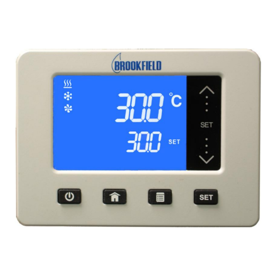
Main Operational Display (Home) This is the Circulators main operational display. You can return to this screen at any time by pressing the key. Lit when heating Actual bath temperature Lit when refrigerating (Refrigerating/Heating models only) Set point temperature Lit when circulating bath fluid Set-Up Sub-Menus Pressing the... -
Page 25: Adjusting The Temperature Set Point
Adjusting the Temperature Set Point This is the temperature at which the fluid in your Circulating Bath will be maintained. It may be set to one- tenth of a degree over a range of -50.0° to +170.0°C / -60.0° to +340°F. The factory default set point is +20.0°C / +68.0°F. -
Page 26: Selecting The Temperature Unit
Selecting the Temperature Unit The temperature units sub-menu (°C / °F) allows you to select the temperature unit in which the actual bath temperature and set point temperature are displayed. The factory default is °C. Touch top arrow for degrees C Touch bottom arrow for degrees F To Access: Press the... -
Page 27: Selecting The Pump Speed
Selecting the Pump Speed This sub-menu allows you to select your Circulator’s pump speed. The choices are Low (LO) and High (HI); the factory default is High (HI). Touch top arrow to select High Touch bottom arrow to select To Access: Press the key until PUMP appears on the display. -
Page 28: Calibrating Your Circulator
Calibrating Your Circulator This sub-menu allows you to match the Circulator’s temperature display to an external reference thermometer. A value from -3.0° to +3.0°C may be entered; the factory default is 0.0°C. IMPORTANT: To prevent Offset Calibration value from being changed unintentionally, the following power down/power up sequence is required to enable the Calibration function. -
Page 29: Setting The Low Limit Temperature
Setting the Low Limit Temperature This sub-menu allows you to limit how low the temperature set point may be set. It also serves as a low limit safety, alerting you if bath temperature falls below the low limit temperature setting. The Low Limit value may be set from -52°... -
Page 30: Setting The High Limit Temperature
Setting the High Limit Temperature This sub-menu allows you to limit how high the temperature set point may be set. It also serves as a high limit safety, alerting you if bath temperature rises above the high limit temperature setting. The High Limit value may be set from +25°... -
Page 31: Selecting The Serial Communication Baud Rate
Selecting the Serial Communication Baud Rate This sub-menu allows you to select the speed at which your Circulator will transmit data. The setting on both the Circulator and the device it is connected to should match. The baud rate setting may be 1200, 2400, 4800, 9600, 19200;... -
Page 32: Setting The Auto Cool Temperature
Setting the Auto Cool Temperature This sub-menu is displayed only on Refrigerating / Heating Circulators. It determines the bath temperature at which refrigeration will be activated and permits more precise control when operating at high temperatures as well as more rapid cool downs. For most applications, an Auto Cool set point 15°C above room temperature is recommended. -
Page 33: Changing Your Circulator's Viewing Angle
Changing Your Circulator’s Viewing Angle Your Circulator is equipped with Swivel 180™, an innovative feature which permits viewing of the temperature display from anywhere over a 180° arc. There are positive stops at 45° intervals; however, the viewing angle may be set NOTE: anywhere within a 180°... -
Page 34: Display Messages And Alarms
Display Messages and Alarms Message and/or Description Corrective Action Symbol Informational Message: Indicates that electrical power was lost during operation or Using the key, turn the Circulator OFF and then back ON. FAIL POWER that the Circulator was turned This will clear the message. OFF using only the power switch/circuit breaker on the rear of the unit. -
Page 35: Routine Maintenance And Troubleshooting
Routine Maintenance and Troubleshooting WARNING: Always turn your Circulator OFF and disconnect it from the electrical power outlet before performing any maintenance or service. WARNING: To avoid the potential for burns, allow the Circulator to cool completely before cleaning or performing any maintenance. WARNING: Always drain all fluid from the reservoir before moving or lifting your Circulator. -
Page 36: Checking The Over-Temperature Safety System
Checking the Over-Temperature Safety System Your Circulator incorporates over-temperature protection according to IEC 61010. For optimum safety, this system should be checked for proper operation at least every six months. This check must be performed with the unit running. 1. Press , enter a temperature set point of approximately 50°C, and then allow the bath to stabilize at that temperature. -
Page 37: Cleaning Your Circulator
Cleaning Your Circulator WARNING: It is the user’s responsibility to properly decontaminate the unit in the event hazardous materials are spilled on exterior or interior surfaces. Consult the manufacturer if there is any doubt regarding the compatibility of decontamination or cleaning agents. Temperature Controller Turn the Temperature Controller OFF by pressing and unplug power cord from the electrical outlet. -
Page 38: Temperature Controller Removal And Re-Installation
Temperature Controller Removal and Re-Installation Removal The Temperature Controller on your Circulating Bath is designed to be easily removed from the top deck without the use of special tools. It is removed as follows: 1. Place the tip of a small flat blade screwdriver under the retaining ring locking tab and pry up gently. -
Page 39: Re-Installation
Re-Installation The top deck of your Circulator incorporates four pins to facilitate positioning of the Temperature Controller when it is being reinstalled. These pins correspond to keyhole slots on the interior of the Circulator’s retaining ring. 1. With the retaining ring locking tab oriented above one of the indents on the top deck, slowly lower the Temperature Controller into the top deck opening until it is resting on top of the positioning pins. -
Page 40: Troubleshooting Chart
Troubleshooting Chart Problem Possible Causes Corrective Action Unit does not run No power to unit Check that the electrical cord is secure and (Digital Display is connected to an operating electrical outlet. blank) Unit does not run Unit in Standby mode Press Power Key on front panel. - Page 41 Problem Possible Causes Corrective Action Insufficient cooling Dust build up on air filter or Clean air filter and/or condenser as required. condenser Blocked air ventilation Remove blockages as required. screens Temperature set point is Decrease temperature set point. too high Excessive heat load Check that heat load does not exceed capacity of bath;...
-
Page 42: Technical Information
Technical Information Reservoir Fluids Depending on your needs, a variety of fluids can be used with your Circulator. No matter what bath fluid is selected, it must be chemically compatible with the reservoir and the materials in your Circulator. It must also be suitable for the desired temperature range. -
Page 43: Application Notes
WARNING: DO NOT USE THE FOLLOWING LIQUIDS: • Automotive antifreeze with additives** • Hard tap water** • Deionized water with a specific resistance > 1 meg ohm • Any flammable fluids • Concentrations of acids or bases • Solutions with halides: chlorides, fluorides, bromides, iodides or sulfur •... -
Page 44: Using Bath Controller With Compatible Brookfield Engineering Software
Using Bath Controller with Compatible Brookfield Engineering Software The controller may communicate with compatible Brookfield Engineering Software. The controller must be connected to the computer with the appropriate RS232 serial cable. RS232 Protocol — Rheocalc Software uses the following RS232 protocol: Data bits —... -
Page 45: Rs232 - For Use Without Brookfield Software (For Customers Using Their Own Software)
RS232 — For use without Brookfield Software (for customers using their own software) Serial Connector — A 9-pin D connector is provided on the back of the Temperature Controller for RS232 data communication. A serial cable that uses only the following pins should be used to connect the Temperature Controller to the computer: Pin #2 —... - Page 46 Legend: ssss Set point (multiplied by 10) tttt Temperature (multiplied by 10) mmmm Ramp time in minutes and tenths of minutes (multiplied by 10) Temperature units digit (F or C) xxxxxx Controller ID (TC-501 for all models) Controller status (1 or 2) Controller Status [z}: Controller ON, in RUN mode Controller OFF, in STANDBY mode...
-
Page 47: Equipment Disposal (Weee Directive)
Equipment Disposal (WEEE Directive) This equipment is marked with the crossed out wheeled bin symbol to indicate it is covered by the Waste Electrical and Electronic Equipment (WEEE) Directive and is not to be disposed of as unsorted municipal waste. Any products marked with this symbol must be collected separately, according to the regulatory guidelines in your area. -
Page 48: Replacement Parts, Optional Accessories & Fluids
Replacement Parts. Optional Accessories & Fluids Replacement Parts, Standard Digital Controller Part Number BEL Bypass Tubing Kit. Short hose with internal spring connecting the inlet and outlet ports PS510-711 of the circulator. Hose Fittings (SD). 1/4" male NPT x 1/4" barb nylon fitting PS300-048 Beaker Platform, small. -
Page 49: Warranty Repair And Service
Warranty Repair and Service Brookfield TC-Series Circulating Temperature Baths are guaranteed for two years from date of purchase against defects in materials and workmanship. The temperature baths must be returned to Brookfield Engineering Laboratories, Inc. or to the Brookfield dealer from whom it was purchased for warranty service. - Page 50 Manufactured by: PolyScience 6600 W. Touhy Avenue Niles, IL 60714 U.S.A. 1-800-229-7569 ● 1-847-647-0611 www.polyscience.com 110-512 BEL/EN...
Need help?
Do you have a question about the BrookField TC Series and is the answer not in the manual?
Questions and answers