Table of Contents
Advertisement
Advertisement
Table of Contents

Related Manuals for Ametek PARSTAT 3000


Summary of Contents for Ametek PARSTAT 3000
- Page 1 PARSTAT 3000 PARSTAT 3000A Hardware Manual P/N 234551 Rev. B...
- Page 2 PARSTAT 3000, PARSTAT3000A Hardware Manual P/N 234551 Rev. B...
-
Page 3: Table Of Contents
PARSTAT 3000, PARSTAT3000A Hardware Manual P/N 234551 Rev. B Safety Instructions and Symbols ........................5 Cleaning Instructions ............................. 5 INTRODUCTION ..........................6 1.1. General ............................6 1.2. Hardware Circuitry ........................6 1.2.1. Potentiostatic mode ....................... 7 1.2.2. Galvanostatic mode ......................7 1.3. - Page 4 Physical and Power Specifications ..................... 24 4.5. AUXILIARY INTERFACE Pinouts ....................26 4.5.1. Pin Numbers for PARSTAT 3000 Auxiliary connection and Analog Connection....26 4.5.2. Pins Outs for PMC AUX01 Digital Cable................26 4.5.3. Pin Outs for PMC ALG02 Analog Cable ................27 4.6.
-
Page 5: Safety Instructions And Symbols
PARSTAT 3000, PARSTAT3000A Hardware Manual P/N 234551 Rev. B Safety Instructions and Symbols This manual contains up to three levels of safety instructions that must be observed in order to avoid personal injury and/or damage to equipment or other property. These are:... -
Page 6: Introduction
PARSTAT 3000, PARSTAT3000A Hardware Manual P/N 234551 Rev. B INTRODUCTION The PARSTAT 3000 (Figure 1), teamed with the VersaStudio software package, comprises a simple, flexible, and extremely powerful system for performing a wide range of electrochemical techniques. This manual covers models PARSTAT3000 and PARSTAT3000A; the term PARSTAT3000 in the manual text represents both variants unless explicitly identified. -
Page 7: Potentiostatic Mode
1.2.1. Potentiostatic mode In this mode, the PARSTAT 3000 controls the potential at the working-sense electrode with respect to the reference electrode (see Figure 2). The counter electrode is driven to the potential required (consistent with the + 30 V compliance of the control amplifier) to establish the desired working potential. The range over which the working electrode potential can be controlled is the entire + 30 V window. -
Page 8: Software
1.5. Inspecting Your New Instrument As soon as you receive your new PARSTAT 3000, inspect it for shipping damage. If any damage is noted, immediately notify Princeton Applied Research and file a claim with the carrier. Save the shipping container for possible inspection by the carrier. -
Page 9: About This Manual
Chapter 3 shows how to set up the hardware. It describes the functions of the connections and indicator lights, and shows how to connect the PARSTAT 3000 to the host computer and test cell. Chapter 4 gives the physical and electrical specifications of the PARSTAT 3000 including the AUXILIARY and ANALOG connector pinouts. -
Page 10: Safety And Component Placement
RF interference and transient sensitivity. 2.1. Safety Considerations 2.1.1. Line Voltage and Power Cords The PARSTAT 3000 connects to AC MAINS with the provided universal plug set and is rated for: 100 to 240 V AC, 1.8 A 50 / 60 Hz. -
Page 11: Component Placement
0.10 0.00 ABS( CE Output ) Figure 3. Safe Operating Area for PARSTAT 3000 on Energy Storage Devices 2.1.4. Component Placement Before assembling the system, give some thought to component placement. You will of course need convenient access to the computer keyboard and, if applicable, the printer. Depending on the application, you might also need to connect and disconnect the cell leads regularly. -
Page 12: Ventilation
PARSTAT 3000, PARSTAT3000A Hardware Manual P/N 234551 Rev. B 2.2. Ventilation PARSTAT 3000 specifications apply at the nominal line voltage + and at a temperature of 25 C (77 unless otherwise noted. Ambient temperature must not exceed 35 C (95 F). -
Page 13: Parstat 3000 Installation
There is a 4 million data point buffer per PARSTAT 3000 channel. Data collection is not affected by latency in display. The experiment continues to run and data files and display are populated as data transfer happens. -
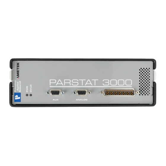
Page 14: Connectors And Indicators
PARSTAT 3000, PARSTAT3000A Hardware Manual P/N 234551 Rev. B 3.3. Connectors and Indicators 3.3.1. Rear Panel The PARSTAT 3000 rear panel is shown in the figure below Figure 4. Rear panel of PARSTAT 3000 3.3.1.1. INPUT POWER 120 to 240 V AC is provided to an external AC/DC converter (“a power brick”) that provides 24 V DC to the instrument. -
Page 15: Front Panel
POWER: This green indicator lights when the PARSTAT 3000 channel is powered on. 3.4. Connecting to the PC and Cell This section gives instructions on connecting the PARSTAT 3000 to the host PC and to electrochemical cell and other equipment. -
Page 16: Connecting The Cell
Though not required, best practice recommends that you first power off the Chassis. Match and attach the D connector side of the Cell cable to the front of the PARSTAT 3000, and secure the screws on either side. After cell cable is connected to front panel, power the unit on and let it boot fully (approximately 1 min to boot up) before connecting a cell to the leads of the cell cable. - Page 17 Yellow – E2 Positive (E2+) electrode lead. This is labelled E2 POS. Along the E2 NEG this is an input to the additional electrometer of the PARSTAT 3000. This is used for 6 -WIRE measurement. Common applications are for Anode/Cathode experiments, measuring single cell in a stack, or any additional external voltage or probe Blue –...
- Page 18 PARSTAT 3000, PARSTAT3000A Hardware Manual P/N 234551 Rev. B b) General aqueous electrochemistry, corrosion experiments and most EIS experiments are connected using a three-terminal connection (Figure 7). The voltage at the working-sense is controlled relative to a stable reference electrode positioned in close proximity to the working electrode.
-
Page 19: Cell Cables And Compatibility
PARSTAT 3000, PARSTAT3000A Hardware Manual P/N 234551 Rev. B After all other connections to the PARSTAT 3000 are made an experiment can be set up and performed. 3.4.3. Cell Cables and Compatibility The cell cable for the PARSTAT 3000 uses a different connector than is used on the other PAR potentiostats. -
Page 20: Setting Operation Modes Of Float And Normal
It is recommend that after one changes modes, a new calibration for DC accuracy be performed by selecting the “Calibrate Now” button above the Flaoting Settings option. In addition to the mode selections, the PARSTAT 3000 also provides additional filters that could be required with some cells in order to enhance the signal to noise. - Page 21 PARSTAT 3000, PARSTAT3000A Hardware Manual P/N 234551 Rev. B Figure 12. Selecting Notch Filters and EIS Filters. The “EIS Filters” are specific for those systems equipped with the FRA option to perform Electrochemical Impedance Spectroscopy (EIS), and can be used when performing EIS techniques where noise pickup from additional, grounded electrodes in the cell are degrading the EIS data.
-
Page 22: Specifications And Pinouts
PARSTAT 3000, PARSTAT3000A Hardware Manual P/N 234551 Rev. B SPECIFICATIONS AND PINOUTS 4.1. Electronic Specifications of the PARSTAT 3000A 4.1.1. System Performance Minimum Time Base: 1 s Minimum Potential Step: 1 uV Minimum Current Range: 4 nA Minimum Current Resolution: 31 fA 4.1.2. -
Page 23: Ir Compensation
PARSTAT 3000, PARSTAT3000A Hardware Manual P/N 234551 Rev. B Resolution: 65536 levels 4.1.8. iR Compensation Positive Feedback Range: 50 MΩ to 5 Ω depending on current range Dynamic iR : 2s/pt rate limit (limited to Corrosion techniques) 4.1.9. Impedance Specifications Frequency Range: 10 μHz –... -
Page 24: Voltage Measurement
Minimum AC Voltage Amplitude : 0.1mV RMS 4.3. Bandwidth Limits The PARSTAT 3000 Power Amplifier has ten bandwidth settings that allow the amplifier's rise time to be slowed in order to maintain stability with the widest possible range of cells. The limits are nominally: 10 MHz, 1 MHz, 500 kHz, 200 kHz, 20 kHz, 2 kHz, 200 Hz, 20 Hz, 2 Hz, 200 mHz. - Page 25 PARSTAT 3000, PARSTAT3000A Hardware Manual P/N 234551 Rev. B Weight 10.5 lbs Dimensions: If placed horizontally: 9.9" W x 3.75" H x 15.8" D If placed vertically with attached support bars: 6" W x 10.33" H x 15.8" D Power Requirements 100 V AC to 240 V AC 50Hz / 60Hz 1.8 A...
-
Page 26: Auxiliary Interface Pinouts
TTL trigger input signal to be read. DISPENSE When using the PARSTAT 3000 with a Model 303 or 303A Static Mercury Drop Electrode (SMDE) via a Model 507 interface, this signal causes the electrode to perform a DISLODGE/DISPENSE operation on command from the host PC. -
Page 27: Pin Outs For Pmc Alg02 Analog Cable
±2V corresponding to +/- full scale current range, 50Ω output impedance. NOTE: If the PARSTAT 3000 channel is operating in “float” mode, then all connections to the Analog Connector must be floating (isolated from ground) as well. If a grounded connection is made to any panel connectors (any non-isolated connection), then the PARSTAT 3000 system will no longer be isolated itself, and ground loops will result in excessively noisy data. -
Page 28: Cell Cable Pinouts
PARSTAT 3000, PARSTAT3000A Hardware Manual P/N 234551 Rev. B 4.6. Cell Cable Pinouts Table 3. PMC Cell Cable Pin Outs Signal Function COUNTER See section 3.4.2. No Connection WORKING See section 3.4.2. SENSE See section 3.4.2. REFERENCE See section 3.4.2. -
Page 29: Available Options
The Advanced Auxiliary Interface (AAI) Option allows for an additional four (4) A/D inputs for the VersaStudio software to acquire along with data recorded directly from every PARSTAT 3000 potentiostat. The AAI is an external unit that plugs directly into the same PC as that interfaced by the PMC potentiostat channel into an available USB port.
Need help?
Do you have a question about the PARSTAT 3000 and is the answer not in the manual?
Questions and answers