
Subscribe to Our Youtube Channel
Related Manuals for Ametek dunkermotoren ServoTube XTR 25


Summary of Contents for Ametek dunkermotoren ServoTube XTR 25
- Page 1 ServoTube XTR 25 Type/Typ XTR 2504 XTR 2506 XTR 2508 Instruction Manual XTR 2510 ServoTube XTR 25 Publication Ref: UM03014/C Betriebsanleitung ServoTube XTR 25 Publikation Ref: UM03014/C...
-
Page 2: Table Of Contents
1 Content 1 Inhalt 2 About this document 2 Über dieses Dokument 3 General description 3 Allgemeine Beschreibung 3.1 ServoTube XTR 25 Actuator 3.1 ServoTube XTR 25 Aktuator 3.2 Standards and Guidelines 3.2 Normen und Richtlinien 4 Sicherheitshinweise 4 Safety Instructions 4.1. -
Page 3: About This Document
2 About this Document 2 Über dieses Dokument These operating instructions introduce you to the Ser- Die vorliegende Betriebsanleitung stellt Ihnen den voTube XTR 25 Actuator and provide you with infor- ServoTube XTR 25 Aktuator vor und informiert Sie mation on all the stages required for the installation of über alle Schritte zur Installation des Antriebs und zur the drive and the performance of functional tests. -
Page 4: General Description
3 Allgemeine Beschreibung 3 General description 3.1 ServoTube XTR 25 Aktuator 3.1 ServoTube XTR 25 Actuator Der ServoTube XTR 25 mit eingebauten Stützlagern The ServoTube high rigidity actuator with integrated ist eine optimale Lösung für Anwendungen mit hohen outrigger-bearings is an ideal solution for applications Seitenlasten. -
Page 5: Standards And Guidelines
3.3 Standards and Guidelines 3.3 Normen und Richtlinien EU guidelines: the EU guidelines formulate the mini- EG-Richtlinien: Die EG-Richtlinien formulieren die mum requirements made on a product and must be ob- Mindestanforderungen an ein Produkt und müssen von served by all manufacturers and dealers marketing the allen Herstellern und Händlern beachtet werden, die product in the member states of the European Union. -
Page 6: Safety Instructions
4 Safety instructions 4 Sicherheitshinweise Vor der Inbetriebnahme sind unbe- Before commissioning, it is dingt die Sicherheitshinweise zu lesen essential that the safety instructions und zu beachten! Eine Nichtbeach- in the relevant section are read, tung kann zu Gefahren bei Personen understood and then observed! WARNING WARNUNG... -
Page 7: Warning Symbols And Meanings
4.1 Warning Symbols and Meanings 4.1 Warnsymbole und Bedeutungen In this User Manual warning symbols are used. These In der vorliegenden Betriebsanleitung werden die un- are intended to alert you to the potential hazards to ten aufgelisteten Warnsignale verwendet. Bitte lesen personnel which are associated with the equipment und befolgen Sie diese sorgfältig. - Page 8 4.1 Warning symbols and meanings 4.1 Warnsymbole und Bedeutungen EMC precautions: This equipment is intended for EMC Sicherheitsvorkehrungen: Das Gerät ist für use in a light industrial environment. It is recommended eine Verwendung in einer Leichtindustrieumgebung that the following precautions be observed during vorgesehen.
-
Page 9: Technical Data
5.Technical Data 5. Technische Daten 5.1 Electrical specification 5.1 Motorspezifikationen 2504 2506 2508 2510 units FORCER TYPE Peak force @ 25 C ambient for 1 sec / Spitzen-Schubkraft @ 25˚C Umgebung, Dauer: 1s Peak current @ 25 C ambient for 1 sec / Spitzenstrom @ 25˚C Umgebung, Dauer:1s With 25 x 25 x 2.5 cm heatsink plate / Mit 25 x 25 x 2.5 cm Kühlkörperplatte Continuous stall force @ 25... -
Page 10: Xtr Force/Velocity Profiles
PEAK PEAK CONTINUOUS CONTINUOUS 5.2 XTR FORCE /VELOCITY PROFILES 5.2 XTR KRAFT/GESCHWINDIGKEITSPROFILE (WITH AN OPERATING VOLTAGE OF 325 VD.C.) (MIT EINER BETRIEBSSPANNUNG VON 325 VD.C.) Velocity (m/s) Velocity (m/s) XTR2504S force/velocity XTR2508P force/velocity XTR2508S force/velocity PEAK PEAK PEAK CONTINUOUS CONTINUOUS CONTINUOUS Velocity (m/s) Velocity (m/s) -
Page 11: Thermal Specifications
5.3 Thermal Specifications / Thermische Daten 2504 2506 2508 2510 units/ FORCER TYPE/ PRIMÄREINHEIT Einheiten Maximum phase temperature/ Max. Phasentemperatur Thermal resistance R / Thermischer 0.39 0.28 0.23 0.19 thphase-housing Widerstand Rth Phase-Gehäuse With 25 x 25 x 2.5 cm heatsink plate/ Mit 25 x 25 x 2,5 cm Kühlkörperplatte Power dissipation @ 25 C ambient/ 65.0... - Page 12 MECHANICAL RIGIDITY (CONTINUED) MECHANISCHE FESTIGKEIT (FORTGESETZT) XTR2504 (-B bush bearing) XTR2506 (-B bush bearing) 1.25 1.25 0.75 0.75 10kg 10kg 0.25 0.25 Extension from zero (mm) Extension from zero (mm) XTR2510 (-B bush bearing) XTR2508 (-B bush bearing) 1.25 1.25 0.75 0.75 10kg...
-
Page 13: Position Sensor
5.5 Position Sensor 5.5 Positionsgeber The position sensor outputs analogue, differential sine Als Positionsrückmeldung gibt der Lagegeber analoge and cosine signals for providing position feedback. Signale, Sinus und Cosinus Differenzsignale aus. Un- Figure C.1 shows the relationships between forcer ten dargestellt ist das Verhältnis zwischen der Gegen- phase back EMF and position sensor outputs for one EMK und der Sensorsignale der Primäreinheit für eine direction of motion (as shown by arrows in Figures C.1... -
Page 14: Forcer Over Temperature Sensor
VALUE UNITS SPECIFICATION WERT EINHEITEN ANGABE Output signal period 51.2 Ausgangssignal-Periode 51.2 Signal amplitude (between +/- signal) Signal Amplitude (zw. +/- Signal) pk-pk pk-pk Output current ±10 Ausgangsstrom ±10 Versorgungsspannung 5 ± 0.25 V d.c. Supply voltage 5 ± 0.25 V d.c. -
Page 15: Cable
Value Units Wert Einheiten SPECIFICATION ANGABE Resistance in the temperature range -20 C to Widerstand im Temperaturbereich von 20 C to 60 to 750 Ohms 60 to 750 Ohms Resistance at 85 <=1650 Ohms Widerstand bei 85 1650 Ohms Resistance at 95 >=3990 Ohms Widerstand bei 95... -
Page 16: Connections
5.8 CONNECTIONS 5.8 Verbindungen Connections within the forcer termination box are as Die folgenden Verbindungen befinden sich innerhalb follows: des Klemmkastens der Primäreinheit: FUNCTION/FUNKTION CONDUCTOR DESIGNATION/ ZUORDNUNG DER LEITUNGEN Forcer phase U/Phase der Primäreinheit U Black 1/ Schwarz 1 Forcer phase V/Phase der Primäreinheit V Black 2/Schwarz 2 Forcer phase W/Phase der Primäreinheit W Black 3/Scwarz 3... -
Page 17: Installation
6 Installation 6 Installation 6.1 UNPACKING 6.1 AUSPACKEN • Check packaging for signs of damage. • Kontrollieren Sie die Verpackung auf Schäden • Metal surfaces may be hot or below • Bei längerer Lagerung können C following prolonged storage. Metaloberflächen heiß sein oder niedriger als 0˚C betragen. -
Page 18: Mechanical Installation-Xtr
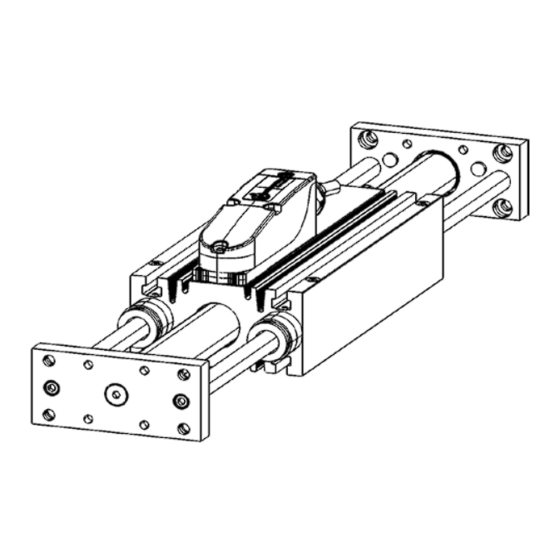
6.3 Mechanische Installation-XTR 6.3 Mechanical Installation-XTR Abbildung 2.1. zeigt eine Zeichnung der Baureihe The outline drawing of the XTR25 is shown in Figure XTR. Die Baureihe XTR besteht aus der Primäreinheit 2.1. It comprises the forcer with dual shafts and bearing mit einem integrierten Plymerlager und der Magnet- bushes. -
Page 19: Electrical Installation
6.5 Elektrische Installation 6.5 Electrical Installation Alle elektronischen Verbindungen zur XTR25 Baurei All electrical connections to the XTR25 are made via two cables, see Figure 2.3a and he erfolgen durch zwei Kabel, siehe Bild Figure 2.3b. One cable carries power to 2.3a und Bild 2.3b. -
Page 20: Maintenance/Service
7. Maintenance/Service 7. Wartung/Service 7.1 Maintenance 7.1 Wartung 7.2. XTR25 7.2 XTR25 The XTR25 series is low maintenance and as such Die XTR Baureihe erfordert geringe Wartung und requires only minimal periodic inspection. muss daher nur minimalen periodischen Inspektionen unterzogen werden. The polymer bearings are dry running, requiring no Die Polymerlager sind trockenlaufend und benöti- lubrication. -
Page 21: Cable Replacement
WARNING! WARNUNG! ISOLIEREN UND TRENNEN SIE ALLE ISOLATE AND DISCONNECT ALL SOURCES OF ELECTRICAL SUPPLY STROMQUELLEN BEVOR SIE MIT DER ARBEIT AM BEFORE WORKING ON THE EQUIPMENT. GERÄT BEGINNEN. 7.3 CABLE REPLACEMENT 7.3 KABEL-AUSTAUSCH Falls ein Kabel ersetzt werden muss, muss man den If a cable needs to be replaced it will be necessary to Klemmkasten öffnen, siehe Bild 3.1. -
Page 22: Replacement
7.4 Replacement 7.4 Einbau von Einzelteilen • Re-fitting is the reverse of the removal procedure. Der Wiedereinbau ist der Umkehrprozess des Aus- bauvorgangs. • Feed the new cable(s) through the cable gland. • Connect the cable(s) including the earth lead. •... -
Page 23: Service
7.5 SERVICE 7.5 SERVICE Should you need to return any items to Dunkermotoren Sollten Sie irgendwelche Teile zu Dunkermotoren Linear Systems, before doing so, please call our Sales Linearsysteme zurückgeben müssen, kontaktieren Sie Department. davor bitte unseren Vertrieb. Please note that when returning items it is recommended Bitte beachten Sie bitte, dass bei Rückgaben that the original packaging be used. -
Page 24: Warranty
8. Apprendices 8. Anhang 8.1 Warranty 8.1 Garantie GARANTIE WARRANTY Dunkermotoren Linear Systems guarantees Dunkermotoren Linear Systems gibt Garantie auf equipment against faulty components for a period fehlerhafte Teile für einen Zeitraum von 12 Monaten of twelve months from delivery. Replacement nach Lieferung des Geräts. -
Page 25: Troubleshooting Chart
8.2 TROUBLESHOOTING CHART 8.2 PROBLEMBEHANDLUNG Check to see if the problem you are experiencing is Kontrollieren Sie ob das auftretende Problem in der listed in the chart below. If the problem cannot be untenstehenden Tabelle aufgeführt ist. Falls das solved with reference to this chart, contact the customer Problem nicht mit Hilfe dieser Tabelle gelöst werden services department. - Page 26 8.3 TERMS AND ABBREVIATIONS TERM DESCRIPTION OF TERM Peak force Peak force is the force produced when the peak current is applied to the forcer. It is the product of Force constant (N/Apk) and Peak current (Apk). The forcer is not moving, there is no forced cooling and no additional heat-sinking.
- Page 27 8.3 TERMS AND ABBREVIATIONS (CONTINUED) Maximum phase Maximum phase temperature is the maximum operating temperature for the motor phases. It is limited to temperature provide a safe operating temperature for the magnets. is the temperature rise from the motor housing to the motor phases for an input power of 1 watt to thphase-houslng thphase-houslng the motor.
-
Page 28: Begriffserklärungen & Abkürzungen
8.3 BEGRIFFSERKLÄRUNGEN & ABKÜRZUNGEN Begriff Beschreibung Spitzen-Schubkraft Die Spitzen-Schubkraft ist diejenige Kraft, die aufgebracht wird, wenn der Motor mit Spitzenstrom versorgt wird. Es ist das Produkt aus der Kraftkonstante (N/A pk) und des Spitzenstroms (A pk). Die Primäreinheit bewegt sich nicht, es erfolgt keine Zwangskühlung und der Motor hat keinen zusätzlichen Kühlkörper. Die Dauer des Spitzenstroms ist thermisch begrenzt und daher nur möglich für einen Zeitraum von 1 Sekunde. - Page 29 8.3 BEGRIFFSERKLÄRUNGEN & ABKÜRZUNGEN (FORTGESETZT) Maximale Die maximale Phasentemperatur ist die maximale Betriebstemperatur für die Motorenphasen. Um eine sichere Phasentemperatur Betriebstemperatur für die Magnete sicherzustellen, ist diese begrenzt. Rth Phase-Gehäuse Rth Phase-Gehäuse ist der Temperaturanstieg innerhalb des Motorgehäuses in Relation zur Temperatur der Motorphasen, bei einer Energiezufuhr zum Motor von 1 Watt.
-
Page 30: Service & Support
9. Service & Support 9. Service & Support Should you have any questions or problems, please Bei Fragen und Problemen stehen Ihnen folgende An- contact: sprechpartner zur Verfügung: - Your local Dunkermotoren sales outlet - Ihre zuständige Vertretung - Your local Dunkermotoren key account manager - Ihr zuständiger Dunkermotoren Key Account - Our hardware support department Manager...
Need help?
Do you have a question about the dunkermotoren ServoTube XTR 25 and is the answer not in the manual?
Questions and answers