Table of Contents
Advertisement
Quick Links
BGE 6010 A / BGE 6015 A
Operation manual BGE 6010 A / BGE 6015 A
Publication Ref: 000000
Betriebsanleitung BGE 6010 A / BGE 6015 A
Publikation Ref: 000000
BGE 6010 A
Dunkermotoren GmbH | Allmendstraße 11 | D-79848 Bonndorf/ Schwarzwald
Phone +49 (0) 7703 930-0 | Fax +49 (0) 7703 930-210/ 212 | info@dunkermotoren.com
Typ:
BGE 6010 A
BGE 6015 A
BGE 6015 A
Part No:
88720.01210
88720.01220
Advertisement
Table of Contents

Related Manuals for Ametek dunkermotoren BGE 6010 A


Summary of Contents for Ametek dunkermotoren BGE 6010 A
- Page 1 BGE 6010 A / BGE 6015 A Typ: Part No: BGE 6010 A 88720.01210 BGE 6015 A 88720.01220 Operation manual BGE 6010 A / BGE 6015 A Publication Ref: 000000 Betriebsanleitung BGE 6010 A / BGE 6015 A Publikation Ref: 000000 BGE 6010 A BGE 6015 A Dunkermotoren GmbH | Allmendstraße 11 | D-79848 Bonndorf/ Schwarzwald...
-
Page 2: Table Of Contents
Content Inhalt 2 About this document ��������������������������������� 6 2 Über dieses Dokument������������������������������ 6 3 General description ����������������������������������� 7 3 Allgemeine Beschreibung ������������������������ 7 ............. 7 ..........7 3.1 Series 3.1 Baureihe ......8 ........8 3.2 Explanation of terms used 3.2 Begriffserklärung .......... - Page 3 ........25 ........ 25 7.14 Analoge Inputs 7.14 Analoge Eingänge ......25 ....25 7.15 Inputs for hall sensors 7.15 Eingänge für Hallsensoren ....... 25 ......25 7.16 Inputs for encoders 7.16 Eingänge für Encoder ......25 ........25 7.17 Auxiliary power supply 7.17 Hilfsspannungen ........
- Page 4 ........41 .........41 9.2.2 mPLC introduction 9.2.2 mPLC Einführung ........41 ........41 9.2.3 Documentation 9.2.3 Dokumentation ....42 .... 42 9.2.4 mPLC system requirements 9.2.4 mPLC Systemvoraussetzungen ..42 .... 42 9.2.5 Installation of the Software mPLC 9.2.5 Installation der Software mPLC ....
- Page 5 Version 07.2020 | Page/ Seite 5 www.dunkermotoren.com...
-
Page 6: About This Document
2 About this document 2 Über dieses Dokument Please read this manual carefully before installing and Lesen Sie diese Betriebsanleitung vor Anschluss und operating the Positioning Controller and follow the instruc- Inbetriebnahme der Positioniersteuerung durch und tions to ensure a flawless operation. Failure to observe this befolgen Sie die Anweisungen um einen störungsfreien rule will invalidate all liability and warranty. -
Page 7: General Description
3 General description 3 Allgemeine Beschreibung 3�1 Series 3�1 Baureihe » The electronic controllers BGE 6010 A and BGE » Bei den Steuerungselektroniken BGE 6010 A und 6015 A are 4-quadrant position controllers with inte BGE 6015 A handelt es sich um 4-Quatdranten- gral output stage and an interface for stand-alone Positioniersteuerungen mit integrierter Endstufe und operation controlled by digital or analogue inouts... -
Page 8: Explanation Of Terms Used
3�2 Explanation of terms used 3.2 Begriffserklärung Explanation Erklärung Term Begriff Version 07.2020 | Page/ Seite 8 www.dunkermotoren.com... -
Page 9: Proper Use
3�3 Proper use 3.3 Bestimmungsgemäße Verwendung » The positioning controller is a vendor part and may » Die Positioniersteuerung ist ein Zulieferteil und darf be used in the configuration described in machines and in der beschriebenen Konfiguration in Maschinen und plants (industrial sector) Anlagen eingesetzt werden (industrieller Bereich). -
Page 10: Safety Instructions
4 Safety instructions 4 Sicherheitshinweise Before commissioning it is essential Vor der Inbetriebnahme sind unbedingt that the safetey instructions are read die Sicherheitshinweise zu lesen und and understood, and then observed! zu beachten. Eine Nichtbeachtung Non-obersvance can result in danger kann zu Gefahren bei Personen oder to persons or damage to the machine. -
Page 11: Technical Data, Accessories
5 Technical data, accessories 5 Technische Daten, Zubehör 5�1 General Performance Data 5�1 Allgemeine Leistungsdaten BGE 6010 A / BGE 6015 A BGE 6010 A BGE 6015 A Performance data/ Leistungsdaten Nominal voltage electronic supply/ 9 ... 30 9 ... 30 Versorgungsspannung Electronic Nominal voltage range power supply/ 9 ... -
Page 12: General Features
5�2 General features 5�2 Allgemeine Eigenschaften BGE 6010 A / BGE 6015 A Description/ Data/ Beschreibung Value Degree of protection to DIN 40050 / IEC 144/ IP 20 Schutzart nach DIN 40050 / IEC 40050 / IEC 144 CAN - CPU electrically connected/ yes / ja CAN - CPU elektrisch verbunden CPU - GND and I/O - GND electrically connected/... -
Page 13: Dimensions
5�3 Dimensions 5�3 Maßzeichnung Heat sink only available with Version BGE 6015 A. Der Kühlkörper ist nur bei Version BGE 6015 A vorhanden. 5.4 Starter Kit (accessory) 5.4 Starter Kit (Zubehör) To use the „Drive Assistant“ software, the user must Um die Software „Drive Assistant“... -
Page 14: Types Of Operation
6 Types of operation 6 Betriebsarten The external controller can be operated in the following Der externe Regler kann in den folgenden Betriebsarten modes: betrieben werden: » Slave in CANopen networks » Slave in CANopen Netzwerken » Stand-alone operation » Stand-alone Betrieb 6�1 Operation with incremental encoder 6�1 Slave in CANopen Netzwerken The operating type „Slave in CANopen networks provides... -
Page 15: Stand-Alone Operation At Stored Running
Velocity Mode by Encoder Velocity Mode per Encoder By selecting a drive equipped with a high resolution enco- Durch den Einsatz eines Antriebs mit Encoder mit einer der a controld circuit can be set up which permits smooth hohen Auflösung wird ein Regelkreis aufgebaut, der rotation and at low speeds. -
Page 16: Installation
7 Installation 7 Installation Before commisioning, it is essential Vor der Inbetriebnahme sind unbedingt that the safety instructions are read die Sicherheitshinweise zu lesen und and understood, and then observed! zu beachten! Eine Nichtbeachtung Non-obersvance can result in danger to kann zu Gefahren bei Personen oder persons or damage to the machine. -
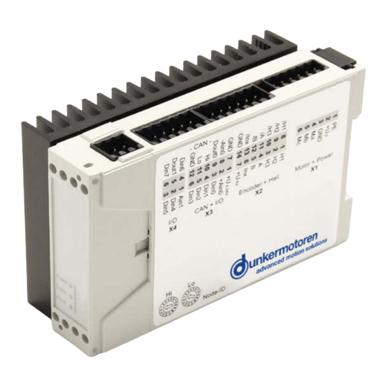
Page 17: Terminal Assignment
Smoothing capacitor: During braking operations, kinetic Glättungskondensator: Bei Bremsvorgängen wird die energy is stored as electrical energy in an intermediate kinetische Energie als elektrische Energie in den Zwi- circuit of the regulation circuit. This can cause excessive schenkreis des Regelkreises zurückgeführt. Dabei kann es voltage in the intermediate circuit, which, in an extreme im Zwischenkreis zu Spannungsüberhöhungen kommen, case, could cause damage to electrical components. -
Page 18: Power Supply And Motor Connections
7�2 Power supply and motor connections 7�2 Versorgungsspannung und Motoranschluss assignment/ Pinbelegung Supply and motor connections BLDC/ Supply and motor connections brush type Versorgungsspannung und ... -
Page 19: Digital Inputs And Outputs
7�3 Hall Sensors/Encoders & analog and 7�3 Hallesonsor/Encoder & analoge und digital inputs and outputs digitale Ein und Ausgänge assignment/ Pinbelegung Terminal/ Beschreibung/ Signal direction/ Klemme Description Signalrichtung Hallsensor signal X2.1 input/Eingang Hallsensorsignal 1... -
Page 20: Connection Brushless Motor
7�4 Connection brushless motor 7�4 Anschluss bürstenloser Motor 12 11 10 9 8 7 6 5 4 14 13 12 11 10 9 8 7�5 Connection brush type motor 7�5 Anschluss bürstenbehafteter Motor Plus (+) Minus (-) 12 11 10 9 8 7 6 5 4 14 13 12 11 10 9 8 Version 07.2020 | Page/ Seite 20... -
Page 21: Connection Hall Sensors
7�6 Connection Hall sensors 7�6 Anschluss Hallsensoren Only with brushless DC motors! Nur bei bürstenlosen Gleichstrommotoren U +5V Hall GND 12 11 10 9 8 7 6 5 4 14 13 12 11 10 9 8 7�7 Connection encoder 7�7 Anschluss Encoder U +5V Encoder GND /Inx... -
Page 22: Connection Power Supply
7�8 Connection power supply 7�8 Anschluss Spannungsversorgung 9 ... 60 V 12 11 10 9 8 7 6 5 4 14 13 12 11 10 9 8 Functional Earth/ Funktionserde 7�9 Connection electronics 7�9 Anschluss Elektronik 9 ... 30 V 12 11 10 9 8 7 6 5 4 14 13 12 11 10 9 8... -
Page 23: Connection Can Interface
7�10 Connection CAN interface 7�10 Anschluss CAN Schnittstelle CAN Low CAN High CAN GND 12 11 10 9 8 7 6 5 4 14 13 12 11 10 9 8 When using the Motion starter kit (SNR 27573.35616), Bei Verwendung des Motion Starterkits (SNR note the following lead assignment: 27573.35616) gilt die folgende Litzen-Zuordnung: White: CAN high... -
Page 24: Digital Inputs
7�12 Digital inputs 7.12 Digitale Eingänge Description/ Beschreibung Number of inputs/ Anzahl Eingänge Input voltage, low (UIN low)/ -30 ... +5 Eingangsspannung Low (UIN low) Input voltage, high (UIN high)/ 8 ... 30 Eingangsspannung High (UIN high) Maximum frequency/ about 500 / ca. 500 Maximale Frequenz 7�13 Digital outputs 7.13 Digitale Ausgänge... -
Page 25: Analoge Inputs
7�14 Analoge Inputs 7.14 Analoge Eingänge Description/ Beschreibung Number of inputs/ Anzahl Eingänge Type/ 1 differential / differentiell 1 x single ended Measurement range/ -10 ... +10 Messbereich Resolution/ 12 bit Auflösung 7�15 Inputs for hall sensors 7.15 Eingänge für Hallsensoren Description/ Beschreibung Number of inputs/... -
Page 26: Status Leds
7�18 Status LEDs 7�18 Status LEDs Blinken Flashing/ = ON = OFF Color/ Status Bedeutung Meaning/ Farbe Power supply is missing/ Versorgungsspannung fehlt LED 0 green/ Normal operation/ grün Normalbetrieb „Power“ green/ Bootloader mode (lack of firmware)/ grün Bootloader Modus (keine Firmware) CANopen Operational state (PDOs active)/ CANopen Operational Zustand (PDOs aktiv) LED 1... -
Page 27: Maintenance & Service & Support
8 Maintenance & Service & Support 8 Wartung & Service & Support 8�1 Maintenance, taking out of service and disposal 8�1 Wartung, Außerbetriebsetzung und Entsorgung Maintenance: Wartung: This drive does not require maintenance if the Bei korrektem Einbau ist der Antrieb wartungsfrei. Wen- installation is carried out correctly. -
Page 28: Commissioning
9 Commissioning 9 Inbetriebnahme When the power supply has been connected, the unit can Ist die Spannungsversorgung hergestellt, kann das Gerät be switched on. The module is then open to access from eingeschaltet werden. Nun kann der softwareseitige Zugriff the software side. auf das Modul erfolgen. -
Page 29: Description Of Main Window
9.1.3 Description of main window 9.1.3 Beschreibung des Hauptfensters In the group fields the configurable modules are shown. In den Gruppenfeldern werden die konfigurierbaren Modi Double clicking on a project make it appear in a new angzeigt. Durch Doppelklicken auf einen gewählten Modus window. -
Page 30: Short Description Of Pi Modules
9.1.5 Short description of PI modules 9.1.5 Kurzbeschreibung PI Module 9.1.5.1 PI 100 Postition module „Standard“ 9.1.5.1 PI 100 Postition module „Standard“ Reference or limit switch Referenz- oder Limitschalter Switch OFF Schalter AUS Switch ON Schalter EIN Function Funktion Clear error and STOP Fehler quittieren und STOP Start Homing Homing starten... -
Page 31: Pi 110 Positioning Module „Stepper
9.1.5.2 PI 110 Positioning module „Stepper“ 9.1.5.2 PI 110 Positioning module „Stepper“ Reference or limit switch Referenz- oder Limitschalter Switch OFF Schalter AUS Switch ON Schalter EIN Function Funktion Clear error and STOP Fehler quittieren und STOP Start homing Homing starten Position 1 (positive) Position 1 (positiv) Position-1 (negative) -
Page 32: Pi 120 Positioning Module „Left-Right
9.1.5.3 PI 120 Positioning module „Left-Right“ 9.1.5.3 PI 120 Positioning module „Left-Right“ Reference or limit switch Referenz- oder Limitschalter Switch OFF Schalter AUS Switch ON Schalter EIN Funktion Funktion Fehler quittieren und STOP Fehler quittieren und STOP Homing starten Homing starten Position 1 Position 1 Position 2... -
Page 33: Pi 130 Positioning Module „Modulo
9.1.5.4 PI 130 Positioning module „Modulo“ 9.1.5.4 PI 130 Positioning module „Modulo“ Reference or limit switch Referenz- oder Limitschalter Switch OFF Schalter AUS Switch ON Schalter EIN Function Funktion Clear error and STOP Fehler quittieren und STOP Start homing Homing starten Position 1 Position 1 Position 2... -
Page 34: Pi 140 Positioning Module
9.1.5.5 PI 140 Positioning module 9.1.5.5 PI 140 Positioning module „Complete positioning command“ „Complete positioning command“ Reference or limit switch Referenz- oder Limitschalter Switch OFF Schalter AUS Switch ON Schalter EIN Funktion Funktion Fehler quittieren und STOP Fehler quittieren und STOP Homing starten Homing starten Position 1... -
Page 35: Pi 150 Positioning Module
9.1.5.6 PI 150 Positioning module 9.1.5.6 PI 150 Positioning module „Positioning by event“ „Positioning by event“ Function Funktion Not used Nicht belegt Rising edge: Start CCW Steigende Flanke: Start CCW 0 ->1 0 ->1 - counter clockwise - gegen den Uhrzeigersinn Rising edge: Start CW Steigende Flanke: Start CW 0 ->1... -
Page 36: Pi 200 Velocity Module
9.1.5.7 PI 200 Velocity module 9.1.5.7 PI 200 Velocity module „Velocity mode standard“ „Velocity mode standard“ Function Funktion Schnellstop, deaktivieren und Fehler Quick STOP, disable and clear error quittieren CCW – gegen den Uhrzeigersinn CCW - counter clockwise CW – im Uhrzeigersinn CW –... -
Page 37: Pi 201 Velocity Module
9.1.5.8 PI 201 Velocity module 9.1.5.8 PI 200 Velocity module „Velocity mode multi“ „Velocity mode multi“ Function Funktion Schnellstop, deaktivieren und Fehler Quick STOP, disable and clear error quittieren CCW – gegen den Uhrzeigersinn CCW - counter clockwise CW – im Uhrzeigersinn CW –... -
Page 38: Pi 300 Current Module
9.1.5.9 PI 300 Current Module 9.1.5.9 PI 300 Current Module „Current mode standard“ „Current mode standard“ Function Funktion Schnellstop, deaktivieren und Fehler Quick STOP, disable and clear error quittieren CCW – gegen den Uhrzeigersinn CCW - counter clockwise CW – im Uhrzeigersinn CW –... -
Page 39: Pi 301 Current Module
9.1.5.10 PI 301 Current Module 9.1.5.10 PI 301 Current Module „Current mode multi“ „Current mode multi“ Function Funktion Schnellstop, deaktivieren und Fehler Quick STOP, disable and clear error quittieren CCW – gegen den Uhrzeigersinn CCW - counter clockwise CW – im Uhrzeigersinn CW –... -
Page 40: Slave In Canopen
9�2 Slave in CANopen 9�2 Slave in CANopen The slave in CANopen network requires the „Motion Start Das Slave in CANopen Netzwerk benötigt das „Motion Kit“ with the software „mPLC“. Start Kit“ mit der Software „mPLC“. (not included) (nicht im Lieferumfang enthalten) For commissioning of the controller a CAN-master is ne- Zur Inbetriebnahme des Reglers ist ein CAN-Master cessary. -
Page 41: Mplc Introduction
9.2.2 mPLC introduction 9.2.2 mPLC Einführung With the mPLC control program, Dunkermotoren provides Mit dem Steuerungsprogramm mPLC bietet Dunkermo- a comprehnsive software tool with which it is possible to toren ein umfangreiches Softwaretool, mit dem es möglich extensively configure the controller. Via the CAN interface, ist verschiedene Regler umfangreich zu konfigurieren. -
Page 42: Mplc System Requirements
9.2.4 mPLC system requirements 9.2.4 mPLC Systemvoraussetzungen Operation system: Windows 7, Windows 8, Windows 10. Betriebssystem: Windows 7, Windows 8, Windows 10. 9.2.5 Installation of the Software mPLC 9.2.5 Installation der Software mPLC When installing the Drive Assistant, mPLC is also automa- Mit der Installation von Drive Assistant wird mPLC automa- tically installed. -
Page 43: Mplc Control Center
If the message „INFO: CAN-USB - not found“ is indica- Sollte im Statusfeld die Meldung „INFO: CAN-USB - not found“ stehen, wurde kein CAN-USB Adapter erkannt. ted in the status field, no CAN_USB adapter was identi- fied. In this case, please examine if the CAN-USB adapter Bitte prüfen Sie, ob der CAN-USB Adapter mit der entspre- is connected to the correct PC interface and if the power- chenden Schnittstelle am PC verbunden ist und ob die... -
Page 44: Python Script
9.2.8 Python Script 9.2.8 Python Script The start of mPLC opens the „Control Center“ in which yo Beim Starten von mPLC öffnet sich das „Control Center“ in can select inter alia „Python Script“. welchem Sie u.a. „Python Script“ anwählen können. Python is a programming language which comprises Python ist eine Programmiersprache, die mehrere Pro- several programming paradigms. - Page 45 In the menu „Script“ you can control the syntax and start Im Menü „Script“ können Sie den Syntax prüfen und das the script. Script starten. In addition there is the possibility to pause and to continue Desweiteren besteht die Möglichkeit, das Script anzuhal- the script as well as to stop it.
- Page 46 Assistance Hilfsmittel „Baud_rate“ „Baud_rate“ A new field appears in which the Baud-rate can be se- Es erschein ein neues Feld in dem die Baud_rate gewählt lected (20k, 50k, 100k, 125k, 500k, 800k, 1000k) and set (20k, 50k, 100k, 125k, 500k, 800k, 1000k) und gesetzt („Set Baud_rate“).
-
Page 47: Can Monitor
9.2.9 CAN monitor 9.2.9 CAN Monitor The CAN monitor is a program to observe and send CAN Der CAN Monitor ist ein Programm, um CAN-Nachrichten messages. Therewith CAN transmissions can be control- zu beobachten und zu senden. Damit lässt sich eine led, supervised, displayed and interpreted. - Page 48 CAN variables be edited as follows: CAN-Variablen können wie folgt bearbeitet werden: Generate a new CAN variable Erzeugen CAN-Variable Edit the selected CAN variable Bearbeiten der ausgewählten CAN-Variable Copy the selected variable Kopieren der ausgewählten CAN-Variable Delete the selected variable Löschen der ausgewählten CAN-Variable The order of CAN objects and variables can be changed Die Reihenfolge von CAN-Objekten und -Variablen kann...
-
Page 49: Configuration
9.2.10 Configuration 9.2.10 Konfiguration The CAN-USB adapter can be configurated with „Hard- Hier kann unter „Hardware“ der CAN-USB-Adapter konfi- ware“. Normally the configuration is set automatically. If guriert werden. Im allgemeinen geschieht dieses automa- the baud rate of the controller should be changed, also tisch. - Page 50 Note regarding the serial adapter respectively the serial Hinweis zum seriellen Adapter bzw. zur seriellen Schnitt- interface: stelle: If your PC / laptop has no serial interface, you should disa- Sollte Ihr PC / Laptop über keine serielle Schnittstelle ver- ble this function here.
-
Page 51: Objects
9.2.10.1 Objects 9.2.10.1 Objekte In dem Bereich „CAN Objects“ werden alle angelegten In the area „CAN objects“ all created CAN objects are CAN Objekte aufgelistet. Es werden folgende Parame- listed. The following parameters are shown column by ter der Objekte spaltenweise angezeigt: column: •Name Free-defineable name of the object... - Page 52 •uint32 unsigned integer 32 bit •uint32 unsigned integer 32 bit - 32 bit whole number without signs - 32 bit ganze Zahl ohne Vorzeichen • float •float floating point number Fließkomma-Zahl •Byte(s) byte assignment of the variable inside •Byte(s) Bytebelegung der Variable innerhalb der the CAN message CAN Nachricht •Factor (a) multiplier...
-
Page 53: Set Up Can Objects
9.2.10.3 Set up CAN objects 9.2.10.3 Anlegen von CAN-Objekten The yellow symbols can be used to setup CAN objects. Zum Anlegen von CAN-Objekten können die gelben Symbole verwendet werden. With the first “New CAN object” you generate a new object, with the next “Edit CAN object” you can modify, Mit dem ersten „New CAN-Objekt“... -
Page 54: Set Up Can Variables
9.2.10.4 Set up CAN variables 9.2.10.4 Anlegen von CAN-Variablen CAN object type PDO CAN Objekt Type PDO With this variable, single bytes of a PDO can be se- Mit dieser Variable lassen sich aus einem PDO einzelne lected, filtered and scaled. The following parameters Bytes selektieren, filtern und skalieren. - Page 55 •Filter active •Filter (Filter Active) • Switching on or switching off the value filter • Einschalten oder Ausschalten des Wertfilters • Kind of the filter (Prohibitive) • Art des Filters (Prohibitive) • Not activated: Only values are • Nicht aktiviert: Es werden nur Werte collected/ recorded, which are inside of the erfasst / protokolliert, die innerhalb der boundary.
-
Page 56: Transmit / Receive
9.2.10.5 Transmit / Receive 9.2.10.5 Senden, Empfangen With the CAN monitor, CAN messages can be transmitted Mit dem CAN Monitor können CAN-Nachrichten gesendet (PC => controller) and received (PC<= controller). There- (PC => Regler) und empfangen (PC <= Regler) werden. fore the required object or the required variable must be Dazu muss das gewünschte Objekt oder die gewünschte selected:... - Page 57 The received objects can be stored as Die empfangenen Objekte lassen sich als “Log_RX-objects” „Log – RX-Objects“-Datei speichern (bzw. speichern These files are in ASCII format (*.Igo). Therefore these unter). Diese Dateien (*.lgo) haben ASCII-Format und files can be opened and edited not only in mPLC, but daher nicht nur mit mPLC sondern auch mit jedem an- also in every other text editor.
-
Page 58: Can Master Of Other Manufacturers
The received objects can be stored as Die empfangenen Objekte lassen sich als “Log_RX-Variables”. „Log – RX-Objects“-Datei speichern (bzw. speichern These files are in ASCII format (*.Igo). Therefore these unter). Diese Dateien (*.lgo) haben ASCII-Format und files can be opened and edited not only in mPLC, but daher nicht nur mit mPLC sondern auch mit jedem an- also in every other text editor. -
Page 59: Communication Settings
9.2.12 Communication settings 9.2.12 Kommunikationseinstellungen Please connect the controller separately (not in the CAN Der Regler ist einzeln (nicht im CAN-Netzwerk) an einen network) to a master (PC). For the initial communication, Master (PC) anzuschließen. Die Kommunikationspara- the parameters have to be set to the factory settings of the meter am Master müssen auf die Werkseinstellungen des controller. -
Page 60: Manufacturer Specific Variant
9.2.12.2 Manufacturer specific variant 9.2.12.2 Herstellerspezifische Variante This variant is more convenient for initial commissioning. Diese Variante ist für die Erstinbetriebnahme besser geeignet. Use of mPLC Verwendung von mPLC •Open and starting the example Script •Öffnen und Starten des Beispiel Scripts “Nodeld_Scan.py”, „Node-Id_Scan.py“, in order to find the node address of the controller... -
Page 61: Test Programs And Other Assistance
* Changing Baud_rate * Ändern der Baud_rate The changes become only effective af- Die Änderungen werden erst nach ter switching off and on the controller! Aus- und Einschalten des Reglers wirksam! When changing the Baudrate, the ma- Beim Ändern der Baudrate ist der ster also has to be configured accor- Master ebenfalls entsprechend zu dingly! - Page 62 Notes/ Notizen Version 07.2020 | Page/ Seite 62 www.dunkermotoren.com...
- Page 63 Notes/ Notizen Version 07.2020 | Page/ Seite 63 www.dunkermotoren.com...
- Page 64 Dunkermotoren GmbH | Allmendstraße 11 | D-79848 Bonndorf/Schwarzwald Phone +49 (0) 7703 930-0 | Fax +49 (0) 7703 930-210/212 | info@dunkermotoren.com...