Table of Contents
Advertisement
Quick Links
Advertisement
Table of Contents
Troubleshooting

Related Manuals for Ametek PMT 40


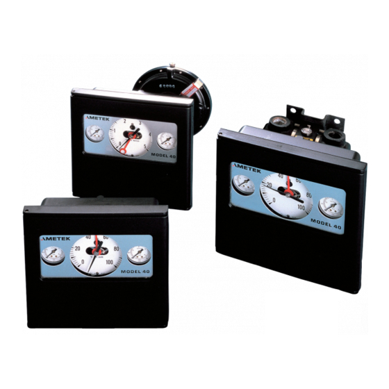
Summary of Contents for Ametek PMT 40
- Page 1 K796131 REV. F 06/2021 Model 40 PNEUMATIC INDICATING CONTROLLER...
- Page 2 These instructions apply to various controllers and their operation, installation and maintenance. Information on variations not covered by these instructions should be requested from AMETEK, PMT PRODUCTS. The customer should be aware that an alternative means of protection of a monitored process may be necessary should this instrument fail.
- Page 3 User Manual MODEL NUMBER INFORMATION Element Control Instrument Element Element Range and Mode Output Type Type Material Units Dial Options Options MODEL 40 See Dial List Pages No Sensing Element 200% Prop + External set point Bronze 300 psi Max Reset (except 160 psi must Overrange Stop...
-
Page 4: Table Of Contents
User Manual TABLE OF CONTENTS INSTALLATION Mounting of Case ............1 Output Connection . - Page 5 User Manual Measuring Element Calibration And Tracking Instructions for All Elements ......14 Bourdon Pressure Elements .
-
Page 6: Installation
User Manual Figure 1 INSTALLATION MOUNTING OF CASE Instrument requires clean, dry, oil-free air. Each controller should be supplied through a standard The instrument should be mounted vertically instrument dripwell-filter and a reducing regulator on a panel, wall, pipe, or valve where it will be with automatic relief valve. -
Page 7: Process Piping
User Manual PROCESS PIPING PRESSURE VESSEL OR LINE CONDENSING PIPE (2" PIPE) 4 FT PRESSURE 1/4" PIPE VESSEL OR LINE PRESSURE 3/8" TUBING INSTRUMENT 1/4" PIPE 3/8" TUBING 1/4" PIPE 1/4" PIPE 3/8" TUBING 3/8" TUBING PRESSURE INSTRUMENT PRESSURE VESSEL OR LINE SUMP PRESSURE VESSEL OR LINE... -
Page 8: Process Connection
User Manual PROCESS CONNECTION SET POINT (Fig. 10) (See Fig. 2 thru Fig. 9) Control point setting is accomplished by turning BEFORE APPLYING PROCESS REFER TO the set point knob to swing the entire outer PRESSURE LIMIT LABEL ATTACHED TO movement up or down around pivot S. -
Page 9: Proportional+ Reset Controller
User Manual PROPORTIONAL + RESET CONTROLLER and the controller operates as a proportional (Fig. 10) instrument. When the reset valve is set to the proper restriction the reset restriction and reset The function of the reset action is to eliminate chamber form a resistance-capacity network the proportional offset between the measuring which at first delays the balance across the... -
Page 10: Proportional + Reset + Rate Controller
User Manual PROPORTIONAL + RESET + RATE With the reset valve closed the instrument acts CONTROLLER (Fig. 10) as a two mode controller (proportional + rate) as described in the previous section. As the reset The function of the three mode controller valve is partially opened, output air is metered (proportional, reset and rate) is to eliminate off into the air chamber outside of the capsule... - Page 11 User Manual DIAL OUTPUT GAUGE SUPPLY GAUGE (OPTIONAL) SET POINTER PROCESS (RED) POINTER (BLACK) CHASSIS RELAY SET POINT KNOB NOZZLE FLAPPER BAND SYNCHRONIZING ADJUSTMENT PROPORTIONAL DIAL Figure 11...
- Page 12 User Manual...
-
Page 13: Tuning Controller To Process Proportional Controller
User Manual TUNING CONTROLLER TO PROCESS reaches. Adjust band to widen or narrow as necessary. Adjust red pointer up or down until PROPORTIONAL CONTROLLER differential gap is at desired level. Red pointer Start up – turn on air and drain dripwell through may be anywhere in the band. -
Page 14: Tuning Proportional + Reset + Rate Controller
User Manual will slowly increase. When output reaches mid- of uncertainly, try about 1/8 of the cycle time span**, quickly turn reset dial counterclockwise noted above. to stop. Output should hold at mid-span. Repeat adjustment of proportional band, which Instrument is now operating as a proportional now may permit a somewhat narrower setting, controller. -
Page 15: Trouble Shooting
User Manual FOR PROPORTIONAL + RESET CONTROLLERS CONTROLLERS To start up manually Open reset valve fully by To start up manually Open reset valve fully turning reset knob clockwise to stop. Open by turning reset knob clockwise to stop. Note rate valve fully by turning rate knob clockwise to controller action (direct or reverse). -
Page 16: Instrument
User Manual INSTRUMENT or utilize a positioner, to prevent movement of the valve from this source. Due to multiplicity of symptoms and causes of trouble, a tabular arrangement for trouble 3. Erratic valve action can occur from sticking shooting in the instrument will facilitate checking. of the stem due to corrosion. -
Page 17: Maintenance
User Manual flexible tubing from output gauge connection). TROUBLE COMMON CAUSES Remove four mounting screws on back of case. Proportional Control Proportional + Reset Control Proportional + Reset + Rate Control Servicing No supply pressure Air supply valve shut, line frozen, regulator not set. Should the exhaust or inlet port become fouled Low supply pressure Regulator not set properly. -
Page 18: Proportional Controller
User Manual To replace Valve and Filter – loosen two valve TO NOZZLE METAL TO METAL SEAL screws (3 turns without removing). Pull up and CONNECTION rotate clockwise until tabs on valve are clear of the OUTPUT GAUGE screw heads. Remove and replace in the reverse order. - Page 19 User Manual FIGURE 14 Figure 14 VALVE SCREW (2) RESET VALVE FEEDBACK LINE (TO RELAY) FILTER BOTTOM “O” RING SPRING LOCKING NUTS VALVE PIN MTG. SCREW (2) ADJUSTING LINK...
- Page 20 User Manual PROPORTIONAL + RESET + RATE Figure 15 FIGURE 15 CONTROLLER (Fig. 15) To replace – same as Proportional + Reset Controller. MTG. SCREW (2) LOCKING NUTS To replace valve and filter – same as Proportional RESET VALVE + Reset Controller. To clean valve and filter –...
-
Page 21: Measuring Element
User Manual MEASURING ELEMENT pointer to avoid bending it. 4. Apply Pu (upper value of scale) to element. All bourdon tube and metal diaphragm elements Note pointer reading. If pointer reads too are interchangeable. high, dimension C must be increased. If the pointer reads too low, dimension C CALIBRATION AND TRACKING must be decreased. - Page 22 User Manual Tighten link screws. proportional band at 10% and proceed with steps 2-5. b. Now restore black pointer to approximately original position by loosening scale shape If instrument is a proportional + reset adjust screw ½ turn and moving the type, trap mid-span output pressure in the segment.
- Page 23 User Manual If instrument is proportional + reset + rate tracking error at Pu. type, turn the rate valve on the feedback b. To increase T (red pointer reads above assembly to its fully open position (clockwise black): loosen lock screw ¼ turn and turn to stop).
-
Page 24: Bourdon Pressure Elements
User Manual BOURDON PRESSURE ELEMENT (Fig. 18) To remove – remove two screws on back of case holding process connection block. Unhook long control link at its lower end. This is the back link, closest to the chassis. Remove shoulder screw to set point link. -
Page 25: Metal Diaphragm Pressure Elements
User Manual METAL DIAPHRAGM PRESSURE ELEMENT (Fig. 19) To remove – remove two screws on back of case holding process connection block. Unhook long control link from lower tab of bell crank. Remove shoulder screw to set point link. Remove three element Figure 26 mounting screws. - Page 26 User Manual To clean indicating assembly – same as Bourdon element. To adjust high pressure stop: 1. Loosen H.P. stop at least 3 turns. 2. Pressure and compound ranges – apply full scale pressure to H. P. side. Vacuum ranges – apply full scale vacuum to L.P.
-
Page 27: Chassis
User Manual Apply Po, Pc and Pu to D/P elements as follows: For pressure and compound ranges – H.P. side with L.P. side vented. For vacuum ranges – L.P. side with H.P. side vented. Chassis (Fig. 23) To remove Chassis – remove element from chassis per instructions under MEASURING ELEMENT. Remove nozzle line and feedback line from relay. -
Page 28: Filter Fittings
User Manual Filter Fittings (Figs. 24, 25) A gradual drop in supply pressure is usually caused by filters being gradually closed up with oil and dirt. This will cause slower controller response which may cause process cycling. Therefore it is good to periodically clean the filters. - Page 29 User Manual REGULATOR KNOB BLUE GREEN D / P AUTO INDICATOR TRANSFER SWITCH MANUAL FEEDBACK NOZZLE RESTRICTOR FLAPPER SUPPLY RELAY TWO POSITION BYPASS CONTROLLER General The two position bypass allows the process to be controlled automatically or manually with provision for bumpless transfer.
-
Page 30: Replacement Parts Lists
User Manual Automatic to Manual – assume process is stable and being controlled by the controller. 1. Adjust the regulator knob until the end of the Differential Pressure indicator bellows is aligned with indicator line. The regulator pressure Pr is then the same as nozzle back pressure Pn. 2. - Page 31 User Manual MATERIAL RANGE BOURDON ELEMENT INCHES HG or PSI PASCAL NEW # PART# -30/0 IN HG -100/0 kPa Z098642 98053 FOR REPLACEMENT DIFFERENTIAL 0/13 to 0/17 PSI 0/90 to 0/110 kPa Z098642 98053 PRESSURE ELEMENTS SPECIFY: Type, 0/25 to 0/35 PSI 0/170 to 0/240 kPa Z098644 98053...
- Page 32 User Manual RECOMMENDED SPARE PARTS MATERIAL RANGE PART NUMBER DESCRIPTION INCHES HG or PSI PASCAL See Table Diaphragm Element Specify Range Dial 0/50 to 0/60 “ H 0/12 to 0/15 kPa NI-SPAN C P-505-A New #P249505 Control Set Pointer 0/66 to 0/105” H 0/16 to 0/26 kPa P-231-11 New #P032612...
- Page 33 User Manual SLACK DIAPHRAGM ACTUATED PRESSURE ELEMENTS RECOMMENDED SPARE PARTS ITEM PART NUMBER DESCRIPTION Range Housing Assy. *Housing Assy. Pressure Diff. Pressure Inches/Water Pascal (kPa) 98339 98324 0/4.5 to 0/8.4 0/1 to 0/2 98329 98325 0/8.5 to 0/14.5 0/2 to 0/3.6 98330 98326 0/14.6 to 0/24.9...
- Page 34 User Manual K810805 Post Mounting Screw #8 Type F Self-Thread (3 required) H-2025-WG New #H074807 Gasket...
- Page 35 User Manual DIFFERENTIAL PRESSURE ELEMENTS DIAPHRAGM H-6306-L 16 18 VALVE STEM H-6203-F DIAPHRAGM SPACER H-3109-BW DIAPHRAGM ASSY. N-2086-EG STEM SPRING H-202-FA RELAY BIAS SPRING GASKET H-2025-YJ (SEE TABLE) CAP H-1883-AM RECOMMENDED SPARE PARTS ITEM PART NUMBER DESCRIPTION LOAD SPRING H-202-EK Specify Range Dial P-505-A...
- Page 36 User Manual Output gauge Supply gauge (see table) (see table) Push button orifice & cleaner assy. N-2087-A Gasket H-2015-UQ Barb (3) K080112 Gasket (3) K230020 Tubing Mtg. screw (not shown) K270091 (4) 8-32 x .38 K802803 RELAY WITH OUTPUT GAUGE RELAY WITH SUPPLY GAUGE K-800803 K-803801...
-
Page 37: Door & Case Assemblies
User Manual FIGURE 14 DOOR ASSEMBLIES (Includes Door & Items 1 thru 11) 200% PROP. + RESET RESET VALVE ASSY. (SEE TABLE) FIGURE 15 TYPE DOOR ASSY. NEW PART # Standard 99647 K721046 300% PROP. + RESET + RATE W/Shatterproof Glass 99649 K721047 W/External Set Pointer... - Page 38 User Manual RECOMMENDED SPARE PARTS ITEM PART # DESCRIPTION G-114 New#G096900 Glass, standard G-119 New#G100400 Glass, shatterproof N-2127 New#N310700 Shaft, pin & “E” Ring K010088 Bushing, latch K101003 Knob K909001 Wrench K803405 Screw Wrench K110066 Shroud clip ( 2 req’d) K800400 Screw Shroud 4-40 x .12 (2 req’d) K230045...
- Page 39 User Manual PROP BAND CONTROL MOVEMENT CHASSIS ASSEMBLY NEW PART # 100% M-503 99475 K721002 200% M-503 99156 K721002 300% M-503 99799 K721002 CHASSIS ASSEMBLY W/FEEDBACK includes chassis assembly, feedback assembly, and mounting srews. Precalibrated for reversibility and control point alignment. To attach nozzle & feedback tubing to pre-1978 relays, order two k080068 barb assemblies PROP BAND CHASSIS ASSY.
-
Page 40: Relay
User Manual FIGURE 14 OUTPUT FILTER FITTING ASSEMBLY MODIFICATION KIT W/FEEDBACK, VALVE, MTG BRACKETS, SCREWS AND WASHERS FILTERS, DECAL AND INSTRUCTIONS (SET OF 2) FIGURE 15 3-15 OUTPUT SPEC. #99863 SPEC. #99811 6-30 OUTPUT SPEC. #99864 RELAY W/REGULATOR (Recommended Spare Parts) OUTPUT FILTER FITTING ASSEMBLY RESET + RATE MODIFICATION KIT W/FDBK, VALVE,... - Page 41 User Manual TUBING K270118 MTG. SCREW (2) 8-32 x .31 K803803 TUBING K270117 MTG. SCREW (2) 8 – 32 X .50 K802805 RESET VALVE ASSY. K671019 TUBING K270113 MTG. SCREW (2) 8 – 32 X .25 K803802 TUBING K270091 TO RELAY...
-
Page 42: Feedback Assemblies
User Manual MULTI-MODE FEEDBACK ASSEMBLIES... - Page 43 User Manual MULTI-MODE FEEDBACK ASSEMBLY OUTPUT PRESSURE VALVE COMPLETE MODE PASCAL ASSY. ASSY. PART # 200% + Reset 3/15 20/100 kPa K671019 99836 K721028 INCHES 1/4” NPT PRESSURE 200% + Reset 2.31 6/30 40/200 kPa K671019 99837 K721029 (BARTON 224) CONNECTIONS (4) 3.62 58,7...
- Page 44 User Manual PROPORTIONAL FEEDBACK ASSEMBLIES INCHES CAPSULE ASSY. SPRING N-202-AQ FRONT BACK (SEE TABLE) 1/2” NPT (FEMALE) 1/4” NPT (FEMALE) CONNECTION 8.56 5.12 217,4 130,0 1/2” NPT (FEMALE) LINK (SEE TABLE) 4.28 NUT (ZERO ADJ.) H-501-DC 2.56 GAS VENT 2.18 1.37 108,7 -OPTIONAL-...
-
Page 45: Replacement Parts Kits
User Manual REPLACEMENT PARTS KITS... - Page 46 User Manual OPTIONS OPTIONS OUTPUT GAUGE ASSEMBLY Recommended Spare Parts OUTPUT GAUGE ASSEMBLY MTG. SCREWS (2) 8 - 32 X .38 BARS COMPLETE ASSY. K802803 0-30 99851 0-60 99852 0-100 99853 For output gauge only, see page 31 Complete assembly includes output gauge, TUBING bracket, tubing and mounting screw.
- Page 47 User Manual...
- Page 48 User Manual INDICATING CONTROLLER OUTLINE DIMENSIONS...
- Page 49 Order e-mail: mctpmt.sales@ametek.com Sales/Technical Support: +1 215-674-1234 | 205 Keith Valley Road | Horsham, PA 19044 U.S.A. © AMETEK, Inc. All rights reserved. Printed in the U.S.A. K796131 REV. F 06/2021 Specifications are subject to change without notice. Visit our Web site for the most up-to-date information.
Need help?
Do you have a question about the PMT 40 and is the answer not in the manual?
Questions and answers