
Related Manuals for Innovative Technology SMART Coin System


Summary of Contents for Innovative Technology SMART Coin System
- Page 1 Smart Coin System User Manual Page 0 of 28 Smart Coin System User Manual Copyright © Innovative Technology Ltd 2015 GA02033...
-
Page 2: Table Of Contents
DOCUMENT INTRODUCTION Document Issue Copyright Limited Warranty Product Safety Information PRODUCT INTRODUCTION General Description Key Features Typical Applications for the Smart Coin System INSTALLATION Preparation Baseplate Mounting Requirements Mounting the Smart Coin System Connect the unit Configuration 3.5.1 Configuration Button Functions 3.5.2... -
Page 3: Document Introduction
Authorized Reseller, and extending for the length of time stipulated by Innovative Technology Ltd. A list of Innovative Technology Ltd offices can be found in every section of this manual set. If the product proves defective within the applicable warranty period, Innovative Technology Ltd will repair or replace the product. -
Page 4: Product Safety Information
Note on Safety Do not put a hand into the Smart Coin System while power is applied. 2) It is possible for a static charge to be transferred onto the coins during normal operation. -
Page 5: Product Introduction
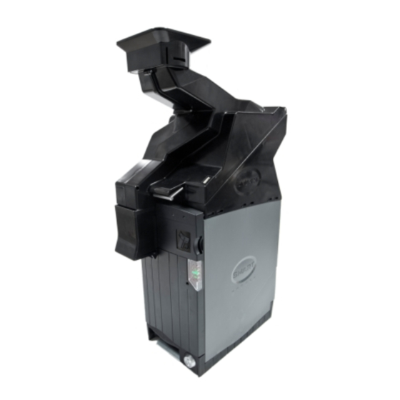
Smart Hopper (SH4) 2.1 General Description The SMART Coin System (SCS) is a state of the art bulk coin validator, mixed coin hopper and recycler in one. The unit validates, discriminates and stores mixed coins, eliminating coin starvation & the need for multiple hoppers. -
Page 6: Typical Applications For The Smart Coin System
2.3 Typical Applications for the Smart Coin System The SMART Coin System can be used in a variety of situations where coin acceptance, validation and recycling are needed. Some typical applications are: • Automated change transactions •... -
Page 7: Installation
Page 6 of 28 3 INSTALLATION 3.1 Preparation If you received your Smart Coin System already mounted on the baseplate, remove it. 3.2 Baseplate Mounting Requirements Ensure that the mounting position and note exit hole meets the dimensional requirements as shown below (all dimensions are in millimetres mm): The coins fall from the cashbox exit chute and are intended to be caught in the host machine cashbox. -
Page 8: Mounting The Smart Coin System
Do not allow screw heads to foul the SMART Coin WARNING! System. Ensure baseplate mounting screws are flush with the surface of the baseplate. 3.3 Mounting the Smart Coin System Slide the Smart Coin System on to the baseplate (reverse of removal). GA02033 Copyright © Innovative Technology Ltd 2015... -
Page 9: Connect The Unit
Apply power to the unit (host machine). 3.5 Configuration The SMART Coin System does not use DIP switches to configure the unit – configuration and setting is carried out by use of a Configuration Button on the front of the SMART Coin System body (below/left of the Led cluster):... -
Page 10: Flash Counts (Interface Type)
Simply copy the Dataset/Firmware file on to the SD Card. Then place the SD Card in to the SD slot on the front of the Smart Coin System. During the update the LED lights will pulse at high speed. Once the update is completed the SMART coin System will reset. -
Page 11: Basic Operation
Page 10 of 28 3.6 Basic Operation The SMART Coin System is a device that can validate, store and later dispense a large number of mixed denomination coins. The SMART Coin System has two Light Emitting Diode (LED) indicators that are used to show the status of the unit (one Red, one Green) –... -
Page 12: Field Maintenance
This section contains the essential information that the field engineer needs to clean, maintain and fault find a SMART Coin System that is installed in a host machine. The SMART Coin System has been designed to minimise any problems or performance variations over time. -
Page 13: Clearing A Jam From The Hopper
Smart Coin System User Manual Page 12 of 28 4.2 Clearing a Jam from the Hopper 1. Power off the SCS and remove 24volt 4 way power cable. 2. Remove the hopper from the mounting plate 3. Empty all coins from the coin bowl 4. - Page 14 Smart Coin System User Manual Page 13 of 28 5. Remove coin cover (fraud cover) Remove fraud cap 6. Re-move the front panel. From the top pull down and right (twist) and the panel clips off. 7. Once the cover is removed check the pistol is not sticking and that the sensor is clean, see picture below.
- Page 15 Smart Coin System User Manual Page 14 of 28 Clean Sensor and pistol. 8. Re-fit all parts 9. Re-attach the hopper to the mounting base plate and the feeder 10. Re-fill the hopper and apply levels to host. 11. Apply power 12.
-
Page 16: Clearing A Jam From The Feeder
Smart Coin System User Manual Page 15 of 28 4.3 Clearing a Jam from the Feeder Before attempting to clear the jam you must ensure the power has been removed. 1. Empty all coins from the funnel. 2. Lift the catch on the front of the feeder and lift the lid back. -
Page 17: Fault Finding - Flash Codes
Smart Coin System User Manual Page 16 of 28 4.4 Fault Finding - Flash Codes The Smart Hopper module has inbuilt fault detection. If there is a configuration or other error, the Smart Hopper module LED’s well indicates will flash in a particular sequence. - Page 18 Smart Coin System User Manual Page 17 of 28 A summary of the Status Indicator Flash Codes for the payout module are shown here: Led Colour Status Description Action Green Flashing Enabled and ready to dispense 1 Flash Hopper disabled Host system to send enables command.
-
Page 19: Mechanical & Electrical Documentation
Smart Coin System User Manual Page 18 of 28 5 MECHANICAL & ELECTRICAL DOCUMENTATION 5.1 Dimensions Copyright © Innovative Technology Ltd 2015 GA02033... -
Page 20: Technical Specifications
Smart Coin System User Manual Page 19 of 28 5.2 Technical Specifications Power Requirements Performance & Reliability Recommended Empty Voltage Weight Full 18kg (approx) Minimum Voltage 21.6V MCBF (cycle) 150,000 Maximum Voltage 26.4V MCBI (cycles) 50,000 Standby Supply Current 200mA... -
Page 21: Earth Bonding
0.7 ohms. Earth resistance. 5.4 Electrical Interfaces SMART Hopper All the connectors needed to set up the SMART Coin System are easily accessible on the bottom base: there are two connectors that are used to allow interfacing and programming: Information... - Page 22 Smart Coin System User Manual Page 21 of 28 Interface communication from the SMART Hopper unit to the host machine can communicate via SSP or CCT. The SSP pin numbering of the socket is shown below, as well as an overview of the...
-
Page 23: Glossary Of Terms
Smart Coin System User Manual Page 22 of 28 6 GLOSSARY OF TERMS Term Meaning Ampere Alternating Current Acknowledge Advanced Encryption Standard ASSY Assembly Average American Wire Gauge Amusement With Prizes Bank Note Validator ccTalk Coin Controls Talk COMMS Communications... - Page 24 Smart Coin System User Manual Page 23 of 28 Innovative Technology Ltd Light Emitting Diode milliampere maximum Multi Drop Bus minimum millimetre millisecond Modified (or Modification) Note Validator Printed Circuit Board Portable Document Format PiPS Pay-in Pay-out System PROM Programmable Read Only Memory...
- Page 25 Smart Coin System User Manual Page 24 of 28 Transistor Transistor Logic Transmit Universal Serial Bus Volt V_In Voltage In WEEE Waste Electrical and Electronic Equipment GA02033 Copyright © Innovative Technology Ltd 2015...
-
Page 26: Cable Drawings
Smart Coin System User Manual Page 25 of 28 7 CABLE DRAWINGS GA02033 Copyright © Innovative Technology Ltd 2015... - Page 27 Smart Coin System User Manual Page 26 of 28 GA02033 Copyright © Innovative Technology Ltd 2015...
- Page 28 Smart Coin System User Manual Page 27 of 28 GA02033 Copyright © Innovative Technology Ltd 2015...
-
Page 29: Contact
Smart Coin System User Manual Page 28 of 28 8 CONTACT MAIN HEADQUARTERS Innovative Technology Ltd Derker Street – Oldham – England - OL1 4EQ Tel: +44 161 626 9999 Fax: +44 161 620 2090 E-mail: support@innovative-technology.co.uk Web site: www.innovative-technology.co.uk BRAZIL suporte@bellis-technology.com.br...
Need help?
Do you have a question about the SMART Coin System and is the answer not in the manual?
Questions and answers