Table of Contents
Advertisement
Quick Links
Advertisement
Table of Contents

Subscribe to Our Youtube Channel
Related Manuals for Innovative Technology BV20


Summary of Contents for Innovative Technology BV20
- Page 1 Doc: GA02118 User Manual BV20 Version: 1.0...
-
Page 2: Table Of Contents
Switching to Programming Mode (SSP) ....................15 4.4.1.5 Programming the device ........................16 4.4.2 DA3 ..............................17 4.4.2.1 General Description ..........................17 4.4.2.2 System Requirements ........................... 17 Copyright © Innovative Technology Ltd 2018 Doc: GA02118/1 User Manual BV20 Version: 1.0 Page 1 of 60... - Page 3 ROUTINE MAINTENANCE ......................... 42 .............................42 NTRODUCTION ......................42 ECOMMENDED LEANING NTERVALS FIRST LEVEL SUPPORT ........................43 LED F ..........................43 EZEL LASH ODES ......................43 ONFIGURATION UTTON UNCTIONS Copyright © Innovative Technology Ltd 2018 Doc: GA02118/1 User Manual BV20 Version: 1.0 Page 2 of 60...
- Page 4 DES E – T ....................56 NCRYPTION RUSTED 11.6 ...........................57 SCROW ONTROL 11.6.1 Escrow Timing Diagram......................58 11.7 ......................59 OWER IMING IAGRAM 11.8 ........................60 AMING ONVENTION Copyright © Innovative Technology Ltd 2018 Doc: GA02118/1 User Manual BV20 Version: 1.0 Page 3 of 60...
-
Page 5: Document Introduction
Authorized Reseller, and extending for the length of time stipulated by Innovative Technology Ltd. A list of Innovative Technology Ltd offices can be found in every section of this manual set. If the product proves defective within the applicable warranty period, Innovative Technology Ltd will repair or replace the product. -
Page 6: Product Safety Information
1.6 Disclaimer Innovative Technology Ltd is not responsible for any loss, harm, or damage caused by the installation and use of this product. This does not affect your local statutory rights. - Page 7 Napájecí svorky a/nebo konektory: Nejsou sledované pro externí kabeláž • Sledovaný stupeň znečištění je: 2 • Následující krytí konečného produktu jsou požadované: Mechanické, Protipožární Copyright © Innovative Technology Ltd 2018 Doc: GA02118/1 User Manual BV20 Version: 1.0 Page 6 of 60...
-
Page 8: Product Introduction
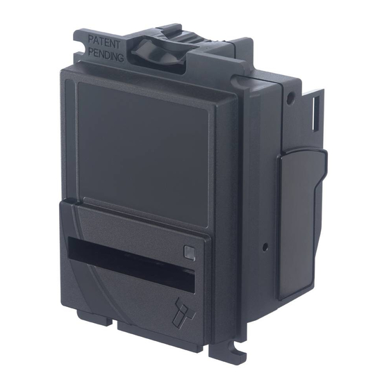
The BV20 is a compact, light-weight bill acceptor ideal for amusement and low value vending applications. Proven field reliability, quick transactions and easy maintenance make the unit future proof. Exceptional value, the BV20 allows a bill acceptor to be installed for the same price as a coin mech. 2.2 Key Features •... -
Page 9: Module Options
The BV20 validator is available with either 66mm or 72mm Bezel. Datasets can only be downloaded to a BV20 with the correct bezel width for the currency. For example a USD dataset can only be downloaded to a 66mm BV20. A Euro dataset can only be downloaded to a 72mm BV20. -
Page 10: Mechanical Installation
No changes to existing machine harnessing are required. 3.1.1.3 Power Supply It is vital that the BV20 is connected to a power supply being able to provide the required power environment. A weak power supply causes malfunctioning of the BV20 such like note rejects or missing credits. -
Page 11: Software Compatibility
3.1.2 Software Compatibility 3.1.2.1 Interface Protocols When using the BV20 as a fitting replacement for an older model or product some events such like credits may be given earlier. This is due to improved firmware routines and faster motors being used. This may cause missing events such like credits in those host machines where timeouts are defined for the older model or product. -
Page 12: Entrance Width Settings
GA02118 User Manual BV20 << Back to Contents 3.2 Entrance Width settings BV20 has 66mm and 72mm bezel width built-in settings available. The two bezels width are not interchangeable. 3.2.1 66mm width setting 1. Check imprinted sizing on top right corner “66mm”... -
Page 13: Cashbox/Baseplate Mounting
<< Back to Contents 3.3 Cashbox/Baseplate Mounting 3.3.1 Cashbox/Baseplate Fitting BV20 is designed to have no built-in cashboxes. Sufficient space behind BV20 must be kept free at all time for accepted banknotes and banknote in escrow to free fall during operation. -
Page 14: Earth Bonding
GA02118 User Manual BV20 << Back to Contents 3.4.2 Earth Bonding It is very important that the BV20 is properly bonded to earth as described in 3.4.1. Lack of proper bonding can cause communication issues and other failures. Caution! Lack of proper earth bonding causes failures! 3.4.3 Screw Specifications... -
Page 15: Software Installation And Configuration
4 SOFTWARE INSTALLATION AND CONFIGURATION 4.1 Introduction The BV20 leaves the factory pre-programmed with the latest dataset and firmware files. However, it is important to ensure your device is kept up to date with the latest dataset and firmware. This section will give you a brief overview of the various update possibilities with the BV20. -
Page 16: Hardware Setup
CN00174 cable to Validator and DA2/IF17. 4.4.1.4 Switching to Programming Mode (SSP) Before programming via the Validator Manager software tool, the BV20 needs to be switched to its programming mode (SSP interface). Please refer to 11.3 for the procedure for doing this. -
Page 17: Programming The Device
Once you have switched the unit into SSP, open Validator Manager and click detect devices. This will scan all active com ports for a unit, if your BV20 fails to connect please ensure the correct drivers are installed and the unit is in SSP. -
Page 18: Da3
• .Net Framework 4 • 256mb ram • 50mb hard disk free • Connected DA3 with active com port optional • Data Flash Card (PA01121) Copyright © Innovative Technology Ltd 2018 Doc: GA02118/1 User Manual BV20 Version: 1.0 Page 17 of 60... -
Page 19: Re-Programming Via Da3
4.4.2.3 Re-programming via DA3 1. Open Device Programming System and add the files you will use. Set “Match” update mode if you want to update current BV20 dataset after comparing datasets or “override” update mode, which will reprogram unit with chosen file and interface not depending on what is downloaded at the moment: 2. -
Page 20: Remote Updates
4. Using small button choose MATCH DOWNLOAD or OVERRIDE DOWNLOAD depending on requirements, then press big button and downloading process will begin. After, the BV20 restart and DA3 button become green colour meaning successful reprogramming. The table below shows an explanation of error codes displayed on the Mode Indicator LED’s if the center RUN button changes colour to red. -
Page 21: Configuration Card
Configuration Card. Manually print and cut off Configuration card (depending on bezel width 66 or 72mm). Power on the BV20 and wait unit the BV20 idles. Press the BV20 configuration button once and enter filled configuration card to validator for changing options/ protocol. -
Page 22: Protocols And Interfacing
GA02118 User Manual BV20 << Back to Contents 5 PROTOCOLS AND INTERFACING 5.1 Introduction The BV20 supports standard industry protocols. Interfaces that are not listed may be available upon request. For any queries regarding interfaces that are not listed please contact support@innovative-technology.com. Caution! -
Page 23: Ssp And Essp
Secure Protocol (SSP) and Encrypted Smiley ® Secure Protocol (eSSP) are field proven secure interfaces specifically designed by Innovative Technology Ltd. to address the problems by cash handling systems in gaming machines. Problems such as acceptor swapping, re-programming acceptors and line tapping are all addressed. -
Page 24: Setup Examples
GA02118 User Manual BV20 << Back to Contents 5.2.3 Setup Examples The drawings below highlights how to connect the BV20 to an SSP or eSSP host machine using available cables and interfaces from Innovative Technology Ltd. For cable drawings please refer to Appendix XYZ. -
Page 25: Cctalk
Not Used Factory Use Only Not Used Factory Use Only Do not connect + Vin Power +12VDC Supply Power 0V Supply (GND) Caution! Copyright © Innovative Technology Ltd 2018 Doc: GA02118/1 User Manual BV20 Version: 1.0 Page 24 of 60... -
Page 26: Cctalk Des Encryption
This exchange is performed in a Trusted Mode maintaining security. The Trusted Mode can only be entered by a physical access to the BV20. Please refer to Appendix XYZ for details. -
Page 27: Sio And Si2
-SIO 9600 Baud -SIO 9600 Baud (Disabled at Start up) – A software enable must be sent to enable the validator. Copyright © Innovative Technology Ltd 2018 Doc: GA02118/1 User Manual BV20 Version: 1.0 Page 26 of 60... - Page 28 Validator Manager Software. The data format according to the Baud rate used is shown in below table Baud Rate Start Bits Data Bits Stop Bits 9600 BV20 will receive and transmit the following event codes. Recognised Transmitted Codes from BV20 Receive Codes to BV20 MESSAGE DECIMAL...
- Page 29 Note Accepted Channel 2 Validator Ready 121➔ Accept on Channel 2 2➔ 172 Accept Note in Escrow Accept Escrow 172➔ Accept on Channel 2 2➔ Copyright © Innovative Technology Ltd 2018 Doc: GA02118/1 User Manual BV20 Version: 1.0 Page 28 of 60...
-
Page 30: Pinout
Do not connect Factory Use Only Do not connect Factory Use Only Do not connect + Vin Power +12VDC Supply Power 0V Supply (GND) Copyright © Innovative Technology Ltd 2018 Doc: GA02118/1 User Manual BV20 Version: 1.0 Page 29 of 60... -
Page 31: Mdb
•MDB address: - 0x30 The BV20 Bank Note Validators have a unique address – 00110XXX binary (30H). The VMC polls the bus to detect presence of the BV20 Validator or get information on the current status of the validator. The validators will respond when asked for activity with an acknowledgment, a negative acknowledgment or a specific reply, depending on its current status. -
Page 32: Pinout
Do not connect Factory Use Only Do not connect Factory Use Only Do not connect + Vin Power +12VDC Supply Power 0V Supply (GND) Copyright © Innovative Technology Ltd 2018 Doc: GA02118/1 User Manual BV20 Version: 1.0 Page 31 of 60... -
Page 33: If5 Interface
5.5.4 MDB PSU Caution! An IF5 cannot be used with BV20110VPSU BV20 can be used with PSU, which allows to use validator directly with MDB applications: Copyright © Innovative Technology Ltd 2018 Doc: GA02118/1 User Manual BV20 Version: 1.0... -
Page 34: Setup Example Drawing/S
GA02118 User Manual BV20 << Back to Contents 5.5.5 Setup Example Drawing/s For MDB PSU mounting: 1. Clip MDB PSU onto BV20’s External Hardware Clip 16-Pin Connector Socket Configuration button External Hardware Clip External Hardware Clip Copyright © Innovative Technology Ltd 2018 Doc: GA02118/1 User Manual BV20 Version: 1.0... - Page 35 GA02118 User Manual BV20 << Back to Contents 2. Plug MDB PSU 20 pin connector into BV20’s 16 pin connector socket: BV20 MDB PSU now installed. Copyright © Innovative Technology Ltd 2018 Doc: GA02118/1 User Manual BV20 Version: 1.0 Page 34 of 60...
-
Page 36: Parallel
1, 2, 3 and 4. The Inhibits are internally held high and must be set to low (GND) to enable banknote acceptance. If no Inhibit is set to low (GND) the Master Inhibit is set and the BV20 is disabled. Copyright © Innovative Technology Ltd 2018 Doc: GA02118/1 User Manual BV20 Version: 1.0... -
Page 37: Escrow Control
11.8 for timing diagram and further details. 5.6.5 Busy Control This is a general-purpose busy signal. It is active low (pin 9) while the BV20 is in operation. 5.6.6 Low Power Mode The Low Power Mode can be used to reduce the power consumption of the BV20 when idle. -
Page 38: Binary
BV20 can be set to give a binary pattern output on the four parallel output pins. If the BV20 is set to Binary it will issue the vend signals as a binary pattern on the parallel outputs for 100 ± 3 ms. In this way a maximum of 15 different notes can be accepted and 4 notes individually inhibited. -
Page 39: Inhibit Control
(GND) the Master Inhibit is set and the BV20 is disabled. 5.7.4 Escrow Control The BV20 has a single note escrow facility. This allows the BV20 to hold onto the note once validated, and then only stack the note into a cashbox when the host machine confirms that the Vend operation has been completed. -
Page 40: Pulse
GA02118 User Manual BV20 << Back to Contents the host machine. The IF9 communicates with the BV20 in serial SSP which gives more security along the length of the cable. The IF9 should be mounted close to the host machine control board where the IF9 converts to the binary connection. -
Page 41: Escrow Control
Low Power Mode! 5.8.7 Credit Hold Function If this function is enabled the BV20 will take the notes as normal but then wait until the escrow line is toggled low/high before it will then give out the pulses per denomination as set. -
Page 42: If15 Interface
The IF15 is connected between the BV20 and the host machine. The IF15 communicates with the BV20 in serial SSP which gives more security along the length of the cable. The IF15 should be mounted close to the host machine control board where the IF15 converts to the pulse connection. -
Page 43: Routine Maintenance
The BV20 has been designed to minimise any performance variation over time. Much of this is achieved by careful hardware and software design. However, depending upon the environment the BV20 may at some time require cleaning, belt changing or note path clearing. -
Page 44: First Level Support
Powered OFF/ON applied setting 7.3 Checking Power and Communication Connections 1. Connect BV20 via TTL-USB adapters, either IF-17 or DA2 should be used. ITL provides principal electrical scheme of IF-17 adapter, please contact support@innovative-technology.co.uk for details. 2. Power supply parameters details are described in Section 10.4. -
Page 45: Program Check Procedure
A ccTalk interface with 16 bit checksum, no encryption will flash 6,1 A ccTalk interface with 8 bit checksum, no encryption will flash 6,1,2 A Binary interface will flash 8,1 Copyright © Innovative Technology Ltd 2018 Doc: GA02118/1 User Manual BV20 Version: 1.0... -
Page 46: Second Level Support
1. Press the Lozenge Release Catch and softly pull open bezel 2. Carefully pull the banknote from behind BV20 until it has come from validator head. 3. Inspect the visible parts of validator of any banknote remains. Then close bezel. -
Page 47: Cleaning The Bv20
The recommended cleaning interval is once a month! 1. Unclip Bezel from BV20 by pressing Lozenge Release Catch and pulling bezel: 2. Wipe dirt and debris away from wheels with a piece of cloth: Copyright © Innovative Technology Ltd 2018 Doc: GA02118/1 User Manual BV20 Version: 1.0... -
Page 48: Clearing A Checksum Error
If error persists, use another Dataset file for downloading to localize problem reason. If error is not disappearing, use EEPROM downloader software. Please, contact support@innovative-technology.com for details. Copyright © Innovative Technology Ltd 2018 Doc: GA02118/1 User Manual BV20 Version: 1.0 Page 47 of 60... -
Page 49: Re-Initialisation Of The Sensors
2. Then click “Initialise” tab: 3. Validator will start initialization procedure. Once the motor run continuously, insert green calibration paper Copyright © Innovative Technology Ltd 2018 Doc: GA02118/1 User Manual BV20 Version: 1.0 Page 48 of 60... - Page 50 GA02118 User Manual BV20 << Back to Contents Copyright © Innovative Technology Ltd 2018 Doc: GA02118/1 User Manual BV20 Version: 1.0 Page 49 of 60...
- Page 51 If some of statuses are red, try to repeat initialization procedure. Having same result, probably validator require repairing/some elements replacing. For initialization file receiving, please, contact support@innovative-technology.co.uk. Copyright © Innovative Technology Ltd 2018 Doc: GA02118/1 User Manual BV20 Version: 1.0...
-
Page 52: Technical Data
Supply Ripple Voltage 0.25 V @ 100 Hz 9.4.2 Supply Currents Supply Current Maximum Standby 0.15 A Running 0.54 A Peak 1.50 A Copyright © Innovative Technology Ltd 2018 Doc: GA02118/1 User Manual BV20 Version: 1.0 Page 51 of 60... -
Page 53: Power Supply Guidance
<< Back to Contents 9.4.3 Power Supply Guidance The BV20 requires a stable 12V DC / 1.7A power supply. Please check the power requirements of your host machine and other peripherals to dimension a suitable power environment for your machine setup. -
Page 54: Compliances And Approvals
10 COMPLIANCES AND APPROVALS 10.1 EC Declaration of Conformity • RoHS • EN Directives • UL • REACH • WEEE • Central Bank Approvals Copyright © Innovative Technology Ltd 2018 Doc: GA02118/1 User Manual BV20 Version: 1.0 Page 53 of 60... -
Page 55: Appendix
GA02118 User Manual BV20 << Back to Contents 11 APPENDIX 11.1 Cable Drawings CN00174 Ribbon Cable (validator to IF-17): 300mm or longer Copyright © Innovative Technology Ltd 2018 Doc: GA02118/1 User Manual BV20 Version: 1.0 Page 54 of 60... - Page 56 GA02118 User Manual BV20 << Back to Contents IF17/IF18/DA3 Power Cable: Copyright © Innovative Technology Ltd 2018 Doc: GA02118/1 User Manual BV20 Version: 1.0 Page 55 of 60...
-
Page 57: Connector Specifications
Female 11.3 Switching to Programming Mode (SSP) Press and Hold the Configuration Button for at least 2 seconds whilst the BV20 is powered up. The Bezel LED will flash rapidly to indicate that SSP is being loaded. Once this process has finished the BV20 will reset. The BV20 will now be in Programming Mode (SSP) and allow connection to a PC via a DA1 or DA2 adapter or connection to a DA3. -
Page 58: Escrow Control
<< Back to Contents 11.6 Escrow Control The BV20 has a single note escrow facility. This allows the BV20 to hold onto the note once validated, and then only stack the note into a cashbox when the host machine confirms that the Vend operation has been completed. If no confirmation of the Vend is received, then the note will be returned to the user after 30 seconds. -
Page 59: Escrow Timing Diagram
GA02118 User Manual BV20 << Back to Contents Caution! Only book the credit on the second Vend pulse! 11.6.1 Escrow Timing Diagram Copyright © Innovative Technology Ltd 2018 Doc: GA02118/1 User Manual BV20 Version: 1.0 Page 58 of 60... -
Page 60: Low Power Mode Timing Diagram
(Time A). When a note is inserted under the front sensor the BV20 wakes up and the busy line goes low to indicate that the validator is in use. The busy line remains low during the validating and stacking process and once the note has been successfully validated and stacked the vend line goes low to issue the credit. -
Page 61: File Naming Convention
<< Back to Contents 11.8 File Naming Convention EUR01207_BV002004182328000_IF_01.bv1 Dataset Code EUR 01 2 07 BV00200 418 2328000 Firmware Code * -Only available for specific validators Copyright © Innovative Technology Ltd 2018 Doc: GA02118/1 User Manual BV20 Version: 1.0 Page 60 of 60...
Need help?
Do you have a question about the BV20 and is the answer not in the manual?
Questions and answers
Какая распиновка у BV -20 и соединить вендисту с 2,5