
Related Manuals for Innovative Technology BV20-1


Summary of Contents for Innovative Technology BV20-1
- Page 1 BV20 Operations Manual BV20-1 Operations Manual Innovative Technology Secure Banknote Handling Solutions Of The Future Page 1 of 48 ® © Copyright Innovative Technology Limited 2007...
- Page 2 Revision History INNOVATIVE TECHNOLOGY LTD Title: BV20 OPERATIONS MANUAL Drawing No Author Date FORMAT GA716 29/07/2007 MS Word 2000 Issue Release Date Modified By Comments Issue 1 15/10/2007 First Issue Page 2 of 48 ® © Copyright Innovative Technology Limited 2007...
-
Page 3: Table Of Contents
Other Interfaces available by request from ITL..............27 USING BV20 CONFIGURATION CARDS................. 28 MECHANICAL INSTALLATION....................29 ROUTINE MAINTENANCE ....................... 30 Re-Calibration ........................31 SUPPORT TOOLS ........................32 10.1 Configuration Cards....................... 32 Page 3 of 48 ® © Copyright Innovative Technology Limited 2007... - Page 4 Appendix B – ESCROW Control ....................37 Appendix C – Interface Tools DA1 – DA2..................38 Appendix D – Configuration Cards....................40 Appendix E – PC System Specification ..................48 Page 4 of 48 ® © Copyright Innovative Technology Limited 2007...
-
Page 5: Introduction
If you require further details please contact the factory. Innovative Technology is not responsible for any loss, harm, or damage caused by the installation and use of this product. This does not affect your local statutory rights. If in doubt please contact Innovative Technology for... -
Page 6: Scope Of Document
IF THE BV20 VALIDATOR IS DISASSEMBLED THE UNIT MUST BE RE-CALIBRATED AND RE INITIALISED, FOLLOWING RE-ASSEMBLY. Innovative Technology Ltd has a policy of continual product improvement. As a result the products supplied may vary from the specification described here. Page 6 of 48 ®... -
Page 7: Environment And Power Requirements
0V To +0.5V +3.7 V +12V Pull up voltage of host 0.6V Outputs with 2K2Ω pull up interface Maximum Current Sink 50mA per output Table 3 - Interface Logic Levels Page 7 of 48 ® © Copyright Innovative Technology Limited 2007... -
Page 8: General Description
The BV20 is designed for easy installation in most machines. Interfacing the Validator is very simple, with the choice of the following protocols: PULSE PARALLEL BINARY CCTALK IF30 IF31 IF32 Table 4 – Available Interfaces/Protocols Page 8 of 48 ® © Copyright Innovative Technology Limited 2007... -
Page 9: Machine Interface: Hardware
The BV20 also has a Configuration Button on the opposite side from the Connector (See Figure 3). Configuration Button 16 Pin Connector External hardware Clip External Hardware Clip Figure 2 – Interface Connector Figure 3 – Configuration Button Page 9 of 48 ® © Copyright Innovative Technology Limited 2007... -
Page 10: Interface Connector Pin Details
Do Not Connect Factory Use Only Do Not Connect Factory Use Only Do Not Connect +Vin Nominal 12V DC supply 0V Supply Table 5 - 16 Pin Connector Details Page 10 of 48 ® © Copyright Innovative Technology Limited 2007... -
Page 11: Configuration Button Functions
Press and hold the Configuration Button Whilst the BV20 powered is off. Apply the power and keep the button pressed for several seconds. The cctalk Encryption key will now be restored to the default setting. Page 11 of 48 ® © Copyright Innovative Technology Limited 2007... -
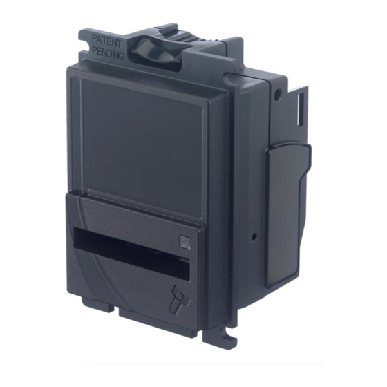
Page 12: Additional Hardware Modules
The modules attach to the back of the BV20 and are held in place by the expansion port clips and a single fixing screw. For unit and cable dimensions please see diagrams below. Figure 4 – BV20 with MDB Voltage Regulator Module Fitted. Page 12 of 48 ® © Copyright Innovative Technology Limited 2007... - Page 14 DO NOT SCALE BV20/100 MDB PSU cable assembly with extended MOD'S TO BE DONE VIA MAGNETIC MEDIA IF IN DOUBT, ASK! length and Y-split end (MDB PSU to host machine) INNOVATIVE TECHNOLOGY LIMITED NOT TO SCALE DERKER ST, OLDHAM 23/07/07 A Lunsong...
- Page 15 FINISH C.A.D. GENERATED DO NOT SCALE BV20 110V PSU to host machine cable MOD'S TO BE DONE VIA MAGNETIC MEDIA IF IN DOUBT, ASK! INNOVATIVE TECHNOLOGY LIMITED assembly NOT TO SCALE DERKER ST, OLDHAM 06/08/07 A Lunsong ENGLAND, Ol1 4EQ...
-
Page 16: Machine Interface: Protocols
It is possible to operate the BV20 in Low power mode with the Parallel interface. For further details please see Chapter 6.4 Page 16 of 48 ® © Copyright Innovative Technology Limited 2007... -
Page 17: Pulse Stream Output
The busy line remains low throughout the whole process and the validator remains inhibited until all pulses are given. Page 17 of 48 ® © Copyright Innovative Technology Limited 2007... -
Page 18: Binary Output - Bin
1 to 4 are inhibited. It is possible to operate the BV20 in Low power mode with the Binary interface. For further details please see Chapter 6.4 Page 18 of 48 ® © Copyright Innovative Technology Limited 2007... -
Page 19: Low Power Option
Low Power mode uses 3 control lines: Vend – Pin 1, Inhibit – Pin 5 and Busy – Pin 9 Inhibit Busy Vend Validating Stacking Figure 11 - Low Power Mode Timing Diagram Page 19 of 48 ® © Copyright Innovative Technology Limited 2007... - Page 20 After the credit is issued the busy line goes high and approximately 1 second after the busy line goes high (Time B) the BV20 goes back into low power mode. Page 20 of 48 ® © Copyright Innovative Technology Limited 2007...
-
Page 21: Serial Input/Output - Sio
Bit 2 Bit 3 Bit 4 Bit 5 Bit 6 Bit 7 Stop Idle 0.1ms =20dec Figure- 5 Typical Serial Output: Transmission of the value 20 (decimal), Note not recognized Page 21 of 48 ® © Copyright Innovative Technology Limited 2007... - Page 22 Enable serial escrow mode Disable serial escrow mode Accept Escrow Reject Escrow Status Enable all Disable all Disable escrow timeout Enable escrow timeout Table 7 - Receive and Transmit Codes Page 22 of 48 ® © Copyright Innovative Technology Limited 2007...
- Page 23 Note entered into validator Validator Busy Note Accepted Channel 2 Validator Ready Accept on Channel 2 Accept Note in Escrow Accept Escrow Accept on Channel 2 Table 8 - Example Protocols Page 23 of 48 ® © Copyright Innovative Technology Limited 2007...
-
Page 24: Smiley® Secure Protocol - Ssp
(Drawing GA 138), this is available from the ITL website www.innovative-technology.co.uk. To help in the software implementation of the SSP, ITL can provide DLL controls and Visual Basic applications on request. Please contact Page 24 of 48 ® © Copyright Innovative Technology Limited 2007... -
Page 25: Multi-Drop Bus / Internal Communications Protocol (Mdb/Icp)
The number of decimal places must also be programmed for each Validator • The number would be set to 2 for Euro or USA • The number would be set to 3 for Columbia Page 25 of 48 ® © Copyright Innovative Technology Limited 2007... - Page 26 • £5 would be displayed as 5.00 • £10 would be displayed as 10.00 • $1 would be displayed as 1.00 • 1K Columbia would be displayed as 1.000 Page 26 of 48 ® © Copyright Innovative Technology Limited 2007...
-
Page 27: Cctalk Protocol - Cct
NIS – Compatible with Mars Non-Isolated Serial Protocol • IF30 – Compatible with ID003 protocol • IF31 – Special interface (Columbia) • IF32 – Compatible with Cash Code CCnet Protocol Page 27 of 48 ® © Copyright Innovative Technology Limited 2007... -
Page 28: Using Bv20 Configuration Cards
It is now possible to check the programmed settings of the BV20 by pressing the Configuration button twice within half a second. (For details see page 2 of Appendix D – Configuration Cards) Page 28 of 48 ® © Copyright Innovative Technology Limited 2007... -
Page 29: Mechanical Installation
BV20-1 Operations Manual 8. Mechanical Installation The BV20 validator is available with either a 66mm or 72mm Bezel. Page 29 of 48 ® © Copyright Innovative Technology Limited 2007... -
Page 31: Routine Maintenance
This can be performed in conjunction with the diagnostics software option in the ITL BNV Currency Manager Program and help menus supplied with this program. Page 31 of 48 ® © Copyright Innovative Technology Limited 2007... -
Page 32: Support Tools
The following support tools are available for use with the BV20 Bank Note Validator: • ITL Bank Note Validator Currency Manager Software. • Configuration Cards. • Validator Programming System (DA3) • Downloads from the Innovative Technology Ltd website: www.innovative-technology.co.uk • E-mail Support via support@innovative-technology.co.uk 10.1... -
Page 33: Internet Website Support
BV20. You can obtain these along with technical bulletins by visiting www.innovative-technology.co.uk 10.5 E-mail Support If the data you require is not available over the Internet Innovative Technology supports an e-mail system to help customers with unusual requirements. The address is: support@innovative-technology.co.uk Page 33 of 48 ®... -
Page 34: Appendix A - Exploded Diagrams
BV20-1 Operations Manual Appendix A – Exploded Diagrams Page 34 of 48 ® © Copyright Innovative Technology Limited 2007... - Page 36 No.4 20x1/4” Pozi Flange BZP PB243 Printed Circuit Board PM773 Motor Cover PA774 Motor Assembly PA773 Drive Axle Assembly MC253 Gear Shaft PM533 Helical Compound Gear PM772 Compound Gear LB155 Strim Sensor Label Page 36 of 48 ® © Copyright Innovative Technology Limited 2007...
-
Page 37: Appendix B - Escrow Control
In the event of a note being forcibly removed from the mouth of the BV20 during the 30-second interval, the BV20 will go out of service for 45 seconds. Page 37 of 48 ® © Copyright Innovative Technology Limited 2007... -
Page 38: Appendix C - Interface Tools Da1 - Da2
NOTE: The Validator must be in Programming mode when connected to a computer and then returned to the Original Settings when the download is complete Figure 9 – Connecting DA1 to BV20 and PC for upgrading Validator programs Page 38 of 48 ® © Copyright Innovative Technology Limited 2007... - Page 39 (GA338) and follow the instructions relating to your specific Operating System. NOTE: All files contained on the CD are available from the ITL Website: http://www.innivative-technology.co.uk Please contact support@innovative-technology.co.uk, if you require further assistance. Page 39 of 48 ® © Copyright Innovative Technology Limited 2007...
-
Page 40: Appendix D - Configuration Cards
BV20 Operations Manual - GA716 Appendix D – Configuration Cards Page 40 of 48 ® © Copyright Innovative Technology Limited 2007... - Page 41 GA 713 BV Configuration Option Progamming Instructions for use Insert this end first 1 - Cut card around outline - check measurements as printed. Check print options ‘Page scaling’ is set to ‘None’ when printing a pdf file to ensure correct size. 2 - Fill in sections as required.
- Page 42 Program Check Procedure To check settings on a programmed unit: 1 - Power on unit. 2 - Click program set button on unit twice (like double click on mouse). 3 - Monitor bezel led and check flash codes on table below Flash count Pulse High Pulse Low Pulse per dollar High speed Disabled cctalk plain cctalk 8 bit low power binary Credit Hold Pulse ms/10...
- Page 43 Insert this end first Insert this end first PULSE PULSE IF 30 IF 30 IF 31 IF 31 CCTALK CCTALK PARALLEL PARALLEL I/F Spare 4 I/F Spare 4 IF 32 IF 32 I/F Spare 1 I/F Spare 1 I/F Spare 2 I/F Spare 2 I/F Spare 3 I/F Spare 3...
- Page 44 Below are some typical examples of completed Configuration Cards. Note: These Configuration Cards are samples and should not be copied for programming use. Please see document GA713 for useable cards. Parallel Binary Page 44 of 48 ® © Copyright Innovative Technology Limited 2007...
- Page 45 BV20 Operations Manual - GA716 Encrypted CCtalk Unencrypted Cctalk with Unencrypted Cctalk 16-bit Checksum with 8-bit Checksum Page 45 of 48 ® © Copyright Innovative Technology Limited 2007...
- Page 46 BV20 Operations Manual - GA716 Pulse – Pulse width 50/50 mS Pulse – Pulse width 50/100 mS 1 Pulse per Dollar 4 Pulses per Dollar Page 46 of 48 ® © Copyright Innovative Technology Limited 2007...
- Page 47 BV20 Operations Manual - GA716 SIO 300-Baud SIO 9600-Baud SIO 300-Baud SIO 9600-Baud Starts Disabled Starts Disabled Page 47 of 48 ® © Copyright Innovative Technology Limited 2007...
-
Page 48: Appendix E - Pc System Specification
The ITL Validator Software has been tested and verified using Windows 2000/XP/Vista on a Pentium based PC System (© Microsoft and Intel). Full functionality cannot be guaranteed on lower specification systems. Page 48 of 48 ® © Copyright Innovative Technology Limited 2007...
Need help?
Do you have a question about the BV20-1 and is the answer not in the manual?
Questions and answers