
Subscribe to Our Youtube Channel
Related Manuals for Innovative Technology BV30


Summary of Contents for Innovative Technology BV30
- Page 1 BV30 User Manual Document Revision - v.1 Exported on 17/05/2024 Copyright © Innovative Technology Ltd 2024...
-
Page 2: Change History
Change History Version Date Comment Current Version (v. 1) May 17, 2024 09:37 Craig Steventon: Initial Release BV30 User Manual – 1... - Page 3 Table of Contents • BV30 Product Information • BV30 Technical Data • BV30 Mechanical Installation • BV30 Software Installation and Configuration • BV30 Protocols and Interfacing • BV30 Routine Maintenance • BV30 First Level Support • BV30 Product Compliance •...
-
Page 4: General Description
The BV30 is a compact, light-weight bill acceptor ideal for amusement and low value vending applications. Proven field reliability, quick transactions and easy maintenance make the unit future proof. Exceptional value, the BV30 allows a bill acceptor to be installed for the same price as a coin mech. Key Features •... -
Page 5: Component Overview
Component Overview BV30 User Manual – 4... -
Page 6: Cashbox Options
The BV30 does not have a built-in cashbox, it is designed to be used in stacker-less/free fall applications. When bank notes are successfully validated the BV30 will transport the note through the validator and drop it out of the back of the unit. - Page 7 BV30 Technical Data Contents • Dimensions • Weight • Environmental Requirements • Power Requirements • Supply Voltages • Supply Currents • Power Supply Guidance • Interface Logic Levels • Reliability Data • Media Requirements BV30 User Manual – 6...
- Page 8 Dimensions Weight Product Weight BV30 Validator 300g BV30 User Manual – 7...
-
Page 9: Environmental Requirements
The BV30 requires a stable 12VDC/1.50A power supply. Please check the power requirements of the host machine and any peripherals connected to the same power supply as the BV30, to ensure that it is capable of meeting the requirements of the BV30. -
Page 10: Interface Logic Levels
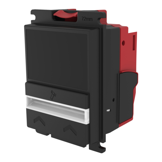
– e.g. clearing a jam. The MCBF of the BV30 is 100,000. Media Requirements Due to the bezel size of the BV30, it cannot accept notes that are wider than 72mm. The minimum and maximum dimensions for notes in are as follows: Dimension... -
Page 11: Hardware Compatibility
It is vital that the BV30 is connected to a power supply capable of providing the required power environment. A weak power supply causes malfunctioning of the BV30 such as note rejects or missing credits. If the BV30 is used as a fitting replacement for an older model or product we recommend to check the power supply specifications of the machine. -
Page 12: Machine Mounting
Older versions of Validator Manager may not support the BV30 Machine Mounting Mounting Points The BV30 has mounting points around the bezel to allow secure mounting to the host machine. Refer to the diagram below for the mounting point locations and measurements: BV30 User Manual – 11... - Page 13 Screw Specification The scope of delivery does not include screws for machine mounting. See table below for the specifications of the mounting screws: Head Diameter Head Height Bolt Diameter Bolt Length Type Flat Head Pan Head BV30 User Manual – 12...
-
Page 14: Software Downloads
However, it is important to ensure your device is kept up to date with the latest dataset and firmware. This section will give you a brief overview of the various update possibilities with the BV30. For detailed instructions please refer to the relevant manual package supplied with the software or contact support@innovative-... -
Page 15: Dataset/Firmware Programming
Connected BV30 with active com port Hardware Setup The connection example below shows how to connect the BV30 to the host machine (PC) using the IF17: We have seen instances where one of the dll’s (itdata1.dll) used in Validator Manager are flagged as a Trojan, this is a false positive and if this happens you will need to add a rule to your antivirus to allow the file to run. - Page 16 Once you have switched the unit into SSP, open Validator Manager and click detect devices. This will scan all active com ports for a unit, if your BV30 fails to connect please ensure the correct drivers are installed and the unit is in SSP.
- Page 17 Disconnect the DA3 from the PC and connect it to the BV30 using a ribbon cable. Ensure that the cable is inserted into the “Validator” connection which is labelled on the back of the DA3. Connect power to the DA3, either using the jack plug connect or using power from the host machine using the “Host Machine”...
- Page 18 Using the small “Mode Select” button choose Match Download or Override Download depending on the file options selected in Step 1. Then press the “Play” button on the DA3 and the downloading process will begin. The LEDs around the button will rotate when the update is in progress. BV30 User Manual – 17...
- Page 19 Download Fail Retry the download. Remote Updates The BV30 supports remote updates via the SSP Protocol. Refer to the SSP implementation guide for information on this remote update process. This is a complex operation and incorrect implementation may damage units. BV30 User Manual – 18...
-
Page 20: Interface Connector
Binary • Pulse Introduction The BV30 supports the industry standard protocols shown in this section. Other interfaces that are not listed may be available on request. For any queries regarding interfaces that are not listed contact support@innovative-technology.com. The use of an encrypted protocol (preferable eSSP) is strongly recommended to achieve the highest... - Page 21 Secure Protocol (SSP) and Encrypted Smiley Secure Protocol (eSSP) are field proven secure interfaces specifically designed by Innovative Technology Ltd. to address the problems by cash handling systems in gaming machines. Problems such as acceptor swapping, re-programming acceptors and line tapping are all addressed. This interface is recommended for all new designs.
- Page 22 Name Type Description Factory Use Only – Do Not Connect +Vin Power +12VDC Supply Power 0V Supply (GND) BV30 User Manual – 21...
- Page 23 Setup Examples The drawing below highlights how to connect the BV30 to an SSP/eSSP host machine using available cables and interfaces from Innovative Technology Ltd. For cable drawings refer to the BV30 Appendix. Type ITL Part Number Description Cable CN00174 Ribbon Cable...
- Page 24 ® When using ccTalk DES encryption, the BV30 and host machine must exchange a secret key which forms the basis of the communication encryption. This exchange is performed in a Trusted Mode maintaining security. The Trusted Mode can only be entered by a physical access to the BV30. Please refer to ccTalk DES...
- Page 25 The use of an encrypted protocol (preferable eSSP) is strongly recommended to achieve the highest security! Pin Assignments Pin Name Type Description Vend1 Output Serial Data Out (Tx) 2 Factory Use Only – Do Not Connect Inhibit 1 Input Serial Data In (Rx) BV30 User Manual – 24...
- Page 26 VMC (Vending Mechanism Controller) is the master that can communicate with up to 32 slaves (e.g. banknote validator or coin acceptor). Contact support@innovative-technology.com for further information. Pin Assignments Name Type Description Vend 1 Output Serial Data Out (Tx) BV30 User Manual – 25...
- Page 27 0V Supply (GND) IF5 Interface An BV30 running MDB can use an IF5, an external interface box, which regulates the power supply and opto-isolates the communication lines. Typically the vending machine’s power supply is a higher voltage than the maximum for the BV30.
- Page 28 MDB PSU An IF5 cannot be used with BV20110VPSU BV30 can be used with MDB PSU, which allows to use validator directly with MDB applications. Parallel General Description Parallel is a 4-way output interface. The first 4 channels have their own individual output which means that only a maximum of 4 channels can be used.
- Page 29 Inhibit 4 Input Inhibit Input Channel 4 by holding HIGH, hold LOW to enable Busy Output Output Busy Signal. Active LOW when BV30 is in transporting, reading or stacking a note Escrow Input Input Escrow Control. Enable escrow function by holding LOW Factory Use Only – Do Not Connect ...
- Page 30 The Low Power Mode can be used to reduce the power consumption of the BV30 when idle. When the Low Power Mode option is set, the BV30 goes into the Low Power Mode after about 6 seconds after the BV30 is powered up and remains in this state until a note is entered.
- Page 31 BV30 can be set to give a binary pattern output on the four parallel output pins. If the BV30 is set to Binary, it will issue the vend signals as a binary pattern on the parallel outputs for 100 ±...
- Page 32 The Low Power Mode can be used to reduce the power consumption of the BV30 when idle. When the Low Power Mode option is set, the BV30 goes into the Low Power Mode after about 6 seconds after the BV30 is powered up and remains in this state until a note is entered.
- Page 33 The IF9 is an interface that allows serial SSP to be used in machines without the need to update the host machine software. The IF9 is connected between the BV30 and the host machine. The IF9 communicates with the BV30 in serial SSP which gives more security along the length of the cable.
- Page 34 The Low Power Mode can be used to reduce the power consumption of the BV30 when idle. When the Low Power Mode option is set, the BV30 goes into the Low Power Mode after about 6 seconds after the BV30 is powered up and remains in this state until a note is entered.
- Page 35 Credit Hold Function If this function is enabled the BV30 will take the notes as normal but then wait until the escrow line is toggled low/ high before it will then give out the pulses per denomination as set. After the pulses have been given, the BV30 will wait for another low/high toggle until the full value of credit pulses are given.
-
Page 36: Recommended Cleaning Intervals
Do not use solvent based cleaners such as alcohol, petrol, methylated spirits, white spirit or PCB cleaner. This will result in permanent damage to the BV30, only use a clean dry cloth or a mild detergent where absolutely necessary. - Page 37 Unclip Bezel from BV30 by pressing Lozenge Release Catch and pulling bezel Wipe dirt and debris away from the wheel and lightpipe with a piece of cloth BV30 User Manual – 36...
-
Page 38: Clearing A Jam
Re-Initialize the Sensors For this procedure, please use ITL Diagnostic Tools (v.2.0.2 and higher) and Green calibration paper LB02191 (FW Version ≥ 4.06 Required). Connect validator using IF-17/DA2 adapter only, open Diagnostic Tools program and choose active com-port BV30 User Manual – 37... - Page 39 Initialize process complete If some of the statuses are red, try to repeat the initialization procedure. If you have the same result the validator will probably require repairing/some elements replacing. To receive the initialization file, please contact support@innovative-technology.com BV30 User Manual – 38...
- Page 40 Bezel Flash Codes The BV30 has built in fault detection facilities. If there is a configuration or other error, the BV30 front bezel will flash to indicate the status. Refer to the table below for a summary of the flash codes:...
-
Page 41: Configuration Button Functions
If there is no communication between the BV30 and the host machine, check that the 16-pin connector is securely connected to the validator and that there is no damage to the cable. With the BV30 powered on, check the protocol that is being used to ensure it is configured correctly for the host machine. Configuration Button Functions explains how to check the protocol. - Page 42 Not all protocols in this table are supported by the BV30, refer to Protocols and Interfacing for a list of supported protocols. BV30 User Manual – 41...
-
Page 43: Ec Declaration Of Conformity
BV30 Product Compliance EC Declaration of Conformity • RoHS • EN Directives • • REACH • WEEE • Central Bank Approvals BV30 User Manual – 42... - Page 44 Escrow Timing Diagram • Low Power Mode Timing Diagram • File Naming Convention • Energy Profile • Purpose of Test • Pass/Fail Criteria • Result • Method & Equipment Used • Conclusion and Recommendations • Compiled By BV30 User Manual – 43...
-
Page 45: Cable Drawings
Cable Drawings CN00174 Ribbon Cable (Validator to IF17) BV30 User Manual – 44... - Page 46 IF17/IF18/DA3 Power Cable BV30 User Manual – 45...
-
Page 47: Connector Specifications
Switching to Programming Mode (SSP) Press and Hold the Configuration Button for at least 2 seconds whilst the BV30 is powered up. The Bezel LED will flash rapidly to indicate that SSP is being loaded. Once this process has finished the BV30 will reset. The BV30 will now be in Programming Mode (SSP) and allow connection to a PC via a DA2 adapter or connection to a DA3. -
Page 48: Cctalk Des Encryption - Trusted Mode
(CCT) interface is set. Click Apply Changes once the validator is configured as required. In DES Trusted mode host requests the security keys of peripheral. Once obtained, the keys need not be transferred again until the BV30 User Manual – 47... -
Page 49: Escrow Control
Escrow Control The BV30 has a single note escrow facility. This allows the BV30 to hold onto the note once validated, and then only stack the note into a cashbox when the host machine confirms that the Vend operation has been completed. If no confirmation of the Vend is received, then the note will be returned to the user after 30 seconds. -
Page 50: Escrow Timing Diagram
Low Power Mode can be used with all none serial communication protocols to reduce the power consumption of the BV30 when idle. When the BV30 is in this state the current consumption is reduced to approximately 1.2mA. The BV20 goes into low power mode approximately 4 seconds after the validator is powered up and remains in this state until a note is entered (Time A). - Page 51 When the Validator is enabled the Inhibit Line is Low and the Busy Line is High. This remains the same until a note is inserted (Time A). When a note is inserted under the front sensor the BV30 wakes up and the busy line goes low to indicate that the validator is in use.
-
Page 52: File Naming Convention
File Naming Convention BV30 User Manual – 51... - Page 53 Pass – Current not exceeding 3A over a prolonged period • Fail – Current exceeds 3A over a prolonged period • 3A is the peak current as stated in the product specification for BV30 Result Picture 1: Power On to Idle Waveform BV30 User Manual – 52...
- Page 54 Picture 2: Idle to Power Off Waveform Picture 3: Idle Waveform BV30 User Manual – 53...
- Page 55 Picture 4: Note Accept Waveform Picture 5: Note Reject Waveform BV30 User Manual – 54...
- Page 56 Note Reject 545187 2.44A 0.36A 0.36A 3.04A 2.88A 3.4A 545195 2.4A 0.28A 0.32A 2.96A 2.88A 3.6A 545198 2.56A 0.28A 0.32A 2.84A 3.08A 3.72A Peaks of > 3A were seen for very minimal time periods (μS). BV30 User Manual – 55...
- Page 57 Method • BV30 downloaded with the latest firmware provided • Oscilloscope connected to the BV30 Channel 1 with Current Probe and Channel 2 with the Voltage Probe • Probes attached to the power lead • Open, Open Choice Desktop and connect to the oscilloscope •...
Need help?
Do you have a question about the BV30 and is the answer not in the manual?
Questions and answers