
Related Manuals for Phenix Technologies LD60


Summary of Contents for Phenix Technologies LD60
- Page 1 Users Manual Phenix Technologies Inc. LIQUID DIELECTRIC TEST SET MODEL NUMBER LD60 VERSION 3.2...
-
Page 3: Table Of Contents
TABLE OF CONTENTS Section Number DANGER DESCRIPTION SPECIFICATIONS INSTALLATION AND GROUNDING INSTRUCTIONS OPERATING INSTRUCTIONS RECALIBRATION ELECTRICAL SCHEMATICS MAINTENANCE AND TROUBLESHOOTING PARTS LIST PARTS ORDERING INFORMATION RETURNED MATERIAL... - Page 4 • DO NOT operate damaged equipment. Remove power, and do not use the equipment until safe operation can be verified by service-trained personnel. Phenix Technologies, Inc. assumes no liability for unsafe or improper use of test equipment.
-
Page 5: Description
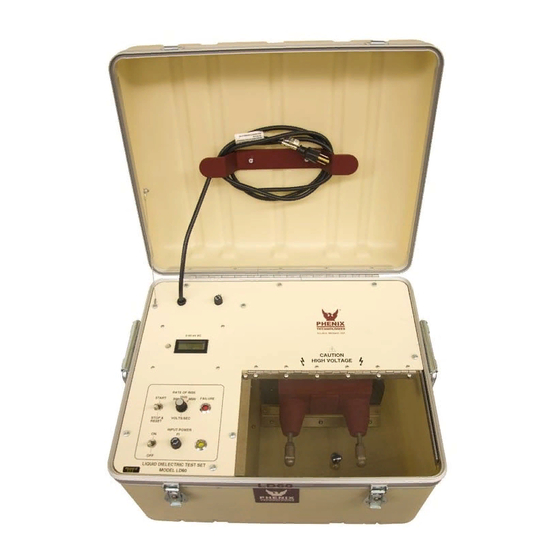
DESCRIPTION The Liquid Dielectric Test Set, Model LD60, is designed to test and measure the dielectric breakdown of insulating oil used in transformers, capacitors, bushings, etc. in accordance to ASTM D877 and ASTM D1816. The standard test set also satisfies the requirements of IEC, VDE, and BS standards. -
Page 6: Specifications
SPECIFICATIONS Input Voltage/Current Single Phase, 120 Volts at 60 Hz, 5 Amps or 220 Volts at 50 Hz, 2.5 Amps (Check Specification Tag) Output Voltage/Power 0-60,000 Volts at 500 VA (momentary), Maximum Voltage to Earth is 30,000 Volts Rate of Rise Selectable—... -
Page 7: Installation And Grounding Instructions
INSTALLATION AND GROUNDING INSTRUCTIONS 1. Place the test set on a table or similar flat surface. 2. Make sure that the test set is level. 3. Open the cover. 4. Check that your input voltage corresponds with the input of the test set. 5. -
Page 8: Operating Instructions
OPERATING INSTRUCTIONS Operation with TC/DE Test Cell (ASTM D877 Standard) Adjust the test cell electrode by the use of the measuring rod located on the test cell in the following manner. Remove the measuring rod by unscrewing it from its threaded holder. Release the setscrew, which holds the adjustable electrode in place on the test cell. - Page 9 OPERATING INSTRUCTIONS Operation with TC/VDE Test Cell (ASTM D1816) 1. Adjust the test cell electrode gap using the double end gauge rod in the following manner. Remove the gauge rod and hex key from the storage block on the side of the cell.
- Page 10 OPERATING INSTRUCTIONS Operation with optional LDCU (Liquid Dielectric Comparison Unit) 1. Make sure power to LD set being checked is turned off. 2. Place the comparison cell in the test chamber of the unit. Plug LDCU ground lead into ground jack. Close transparent cover. 3.
-
Page 11: Recalibration
RECALIBRATION Recalibration of this test set is normally not necessary. For any internal changes, modifications, or calibrations found necessary, please return to the factory. -
Page 12: Electrical Schematics
ELECTRICAL SCHEMATICS Drawing Number Description 9101060 LIQUID DIELECTRIC TEST SET PCB1019 E 31114000 LD60 VM Circuit... -
Page 13: Maintenance And Troubleshooting
MAINTENANCE AND TROUBLESHOOTING Maintenance No maintenance is required besides the control of fuses and control lamps located on the front panel. Ratings of these are described in the parts list. No solution or chemical stronger than ordinary mild soap and water solution should be applied to the cabinet area of this unit. -
Page 14: Parts List
PARTS LIST ITEM DESCRIPTION PART NO. ASSY NO. 8131060, LD60 (120V/240V) FRONT PANEL PC1140 METERING ASSEMBLY 31114000 F1, 2 FUSE HOLDER, 3AGHKP 1603920 F1, 2 FUSE, 3AG-5A 1603605 F1 (220v) 3AG-3A 1603603 PILOT LAMP, YELLOW LED 1420138 PILOT LAMP, RED LED... - Page 15 PARTS LIST ITEM DESCRIPTION PART NO. ASSY NO. 3111941, LD60, PCB 1019 REV. E CAPACITOR 1 uF 250 V 1094130 CAPACITOR .01 uF 1kV 1092050 PC BOARD PCB1019 REV E 1110195 3 PIN PHOENIX CONN. & PLUG 1152603 X2, X6 4 PIN PHOENIX CONN.
-
Page 16: Parts Ordering Information
When your purchase order is received at our office, a representative of Phenix Technologies will contact you to confirm the current price of the part being ordered. If a part you order has been replaced with a new or improved part, an Applications Engineer will contact you concerning any change in part number. -
Page 17: Returned Material
Serial Number Reason for Return Cause of Defect If Phenix Technologies, Inc. deems return of the part appropriate, it will then issue an "Authorization for Return". If return is not deemed advisable, other inspection arrangements will be made. NOTE: Material received at this plant without the proper authorization shall be held as "Customer's Property"...
Need help?
Do you have a question about the LD60 and is the answer not in the manual?
Questions and answers