
Related Manuals for Phenix Technologies PAD56


Summary of Contents for Phenix Technologies PAD56
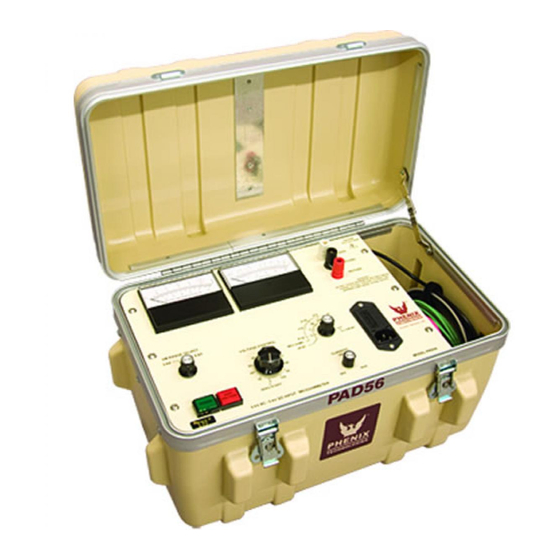
- Page 1 OPERATIONS AND APPLICATIONS MANUAL MODEL NUMBER PAD56 5 KV AC / 6 KV DC HIGH POTENTIAL TESTER WITH MEGOHMMETER Version 2.1 LO/bjf September 23, 2004...
-
Page 3: Table Of Contents
TABLE OF CONTENTS Section Number DANGER PRODUCT INFORMATION -SAFETY AND CAUTION NOTES -DESCRIPTION -SPECIFICATIONS CONTROLS AND CONNECTION -FRONT PANEL CONTROLS AND METERS -INPUT/OUTPUT CONNECTIONS INSTALLATION AND OPERATION INSTRUCTIONS -INSTALLATION -OPERATION -TEST LEAD CONNECTIONS SCHEMATIC PARTS LIST PARTS ORDERING INFORMATION RETURNED MATERIAL... - Page 4 · DO NOT operate damaged equipment. Remove power, and do not use the equipment until safe operation can be verified by service-trained personnel. Phenix Technologies, Inc. assumes no liability for unsafe or improper use of test equipment.
-
Page 5: Product Information
DESCRIPTION The PAD56 tester is capable of producing voltages as high as 6 kV DC (5 kV AC) into a variety of insulated electrical apparatus. The unit will measure leakage current flow through (or insula- tion resistance levels of) the ground insulation of the test sample. Leakage current as low as .01 microamperes DC (.1 milliamperes AC) and as high as 5000 microamperes DC (5 milliamperes... -
Page 6: Specifications
PRODUCT INFORMATION The unit incorporates an overcurrent trip circuit which will instantly de-energize the high voltage power supply if such a condition is encountered. The level of sensitivity at which trip-out will oc- cur is controlled by the front panel adjustment labeled “Min-Max”. The trip setting can be as low as 10% or as high as approximately 110% of full scale reading. -
Page 7: Controls And Connection
CONTROLS AND CONNECTIONS FRONT PANEL CONTROLS AND METERS Raise Voltage: Clockwise rotation of this control increases the tester’s output voltage. The tester’s out- put range is 0-6,000 volts DC or 0-5,000 volts AC. This control must be returned to the “0”... - Page 8 CONTROLS AND CONNECTIONS FRONT PANEL CONTROLS AND METERS (continued) Guard: The guard function is selected by a binding post jumper. When the jumper is connected to “Return”, leakage current or insulation resistance values associated with the “Ground” terminal will be measured. When the jumper is connected to “Guard”, leakage current or insulation resistance associated with the “Ground”...
-
Page 9: Input/Output Connections
CONTROLS AND CONNECTIONS INPUT/OUTPUT CONNECTIONS Return: Leakage current or insulation resistance values associated with this terminal is measured by the “DC Microammeter”. Guard: Leakage current or insulation resistance values associated with this terminal is always bypassed around the “DC Microammeter”. Ground: Leakage current or insulation resistance values associated with this binding post terminal may be either measured by the “DC Microammeter”... -
Page 10: Installation And Operation Instructions
INSTALLATION AND OPERATION INSTRUCTIONS INSTALLATION Install the tester as follows: 1. Turn the main “Power” switch off (out position, non-illuminated). 2. Turn the “High Voltage” power switch off (out position, non-illuminated). 3. Connect the “AC Line” cord to a 115 Volt source. 4. - Page 11 INSTALLATION AND OPERATION INSTRUCTIONS OPERATION (continued) 4. Observe and record the resultant leakage current or insulation resistance value on the “Mi- croamperes/Megohms” meter. If no current reading is indicated, select a lower sensitivity range until an observable reading is obtained at less than full scale on the “DC Micro- am- peres/Megohms”...
-
Page 12: Test Lead Connections
INSTALLATION AND OPERATION INSTRUCTIONS TEST LEAD CONNECTIONS An understanding of the function of the three current return terminals (return, ground, guard) on the tester will allow the operator to properly connect the test leads for a variety of configurations. The following points should be kept in mind when determining the proper connections for a given test requirement: 1. - Page 13 INSTALLATION AND OPERATION INSTRUCTIONS NOTES CONCERNING THE USE GUARD AND GROUND NORMAL MODE CONFIGURATION In this configuration the Return and Ground is connected together with an external jumper or a switch internal to the Test Set, depending on the design. Nothing is connected to the Guard. Both stray leakage to earth ground and leakage through the Test Specimen is indicated on the current meter.
- Page 14 INSTALLATION AND OPERATION INSTRUCTIONS GUARD MODE CONFIGURATION In this configuration the Guard and Ground is connected together with an external jumper or a switch internal to the Test Set, depending on the design. Any current associated with the Return is indicated on the current meter. Any current associated with the Guard bypasses the current meter.
-
Page 15: Schematic
SCHEMATIC Drawing Number Description 9109070 PAD56... -
Page 17: Parts List
SWITCH, ROTARY, 4 POLE 1863045 KNOB FOR ROTARY SWITCH 1355310 POT, 10K, SENSITIVITY ADJ 1761092 KNOB, FOR ABOVE POT 1355305 PAD56 MAIN PCB ASSY PCB 31116904 REGULATOR/HV SECTION BINDING POST RED (RETURN) 1351102 BINDING POST, BLK (GROUND) 1351100 K4-5 HV RELAY... - Page 19 PARTS LIST ITEM DESCRIPTION PART NO. VARIAC 120V PRI., 0-120V, 1.75A, SEC. .231KVA 1890100 TRANSFORMER, 120V PRI., 6000V SEC., 1896050 130VA, JEFFERSON ELECTRIC #720 -33 50VA AUTO XFMR 230V:115V (220V INPUT ONLY) 1894425 STANCOR P-8620 CASE 2100513 SMALL TEST LEAD WIRE (RED) 10’...
-
Page 20: Parts Ordering Information
When your purchase order is received at our office, a representative of Phenix Technologies will contact you to confirm the current price of the part being ordered. If a part you order has been replaced with a new or improved part, an Applications Engineer will contact you concerning any change in part number. -
Page 21: Returned Material
Serial Number Reason for Return Cause of Defect If Phenix Technologies, Inc. deems return of the part appropriate, it will then issue an "Authoriza- tion for Return". If return is not deemed advisable, other inspection arrangements will be made. NOTE: Material received at this plant without the proper authorization shall be held as "Customer's Property"...
Need help?
Do you have a question about the PAD56 and is the answer not in the manual?
Questions and answers