
Subscribe to Our Youtube Channel
Related Manuals for Phenix Technologies 400P


Summary of Contents for Phenix Technologies 400P
- Page 1 USER’S MANUAL CONJUNTO DE TESTE DIELÉTRICO DC - 400P MODELO 4100-10 VERSÃO 5.4 Phenix Technologies Inc. 75 Speicher Drive Accident, MD 21520 Copyright © Phenix Technologies, Inc Rev 8/27/2021 ARF II DCD 4100-10...
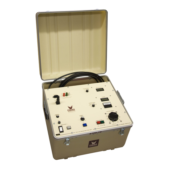
- Page 2 INTRODUÇÃO A linha DC Hipot oferecida pela Phenix Technologies é robusta e adequada para uso em campo ou laboratório. Ele é projetado para testar disjuntores, cabos, motores, geradores e equipamentos de proteção. O teste DC é popular porque o equipamento é mais compacto e mais leve do que o equipamento AC comparável.
- Page 3 ÍNDICE DESCRIÇÃO SEÇÃO INTRODUÇÃO PERIGO / PRECAUÇÕES GERAIS DE SEGURANÇA ESPECIFICAÇÕES TÉCNICAS CONTROLES E INDICADORES CONFIGURAÇÃO ELÉTRICA INSTRUÇÕES DE OPERAÇÃO PAINEL FRONTAL DE CONEXÃO GROUND-GUARD CALIBRAÇÃO SOLUÇÃO DE PROBLEMAS ARMAZENAGEM DO EQUIPAMENTO SIMBOLOS DO DIAGRAMA DE CIRCUITOS SOBRESSALENTES RECOMENDADOS / LISTA DE PEÇAS INFORMAÇÕES PARA PEDIDO DE PEÇAS MATERIAL DEVOLVIDO DIAGRAMAS ELÉTRICOS...
-
Page 4: General Safety Precautions
• NÃO opere equipamentos danificados. Desligue a alimentação e não use o equipamento até que a operação segura possa ser verificada por pessoal treinado para manutenção. A Phenix Technologies, Inc. não assume nenhuma responsabilidade pelo uso inseguro ou impróprio de equipamentos de teste... - Page 5 SEÇÃO 1: ESPECIFICAÇÃO TÉCNICA Entrada 120 VAC 10 Amps or 220 VAC 5 Amps, 50/60 Hz, monofásico (consulte a etiqueta de dados da unidade) Saída (máxima) 0-100 kilovolts dc 0-10 milliamperes fuga resistiva contínua 0-20 milliamperes carregamento capacitivo de curto prazo Capacidade de descarga interna: 6 kilojoules Ciclo de Trabalho Contínuo - Carregamento Capacitivo...
-
Page 6: Painel De Controle
SEÇÃO 2: CONTROLES E INDICADORES PAINEL DE CONTROLE (Ref. a Figura 2-1). 1. ENTRADA DE ALIMENTAÇÃO AC . Conecte em uma tomada adequadamente aterrada. Consulte a etiqueta de especificações na unidade para obter os requisitos de tensão e corrente. 2. BLOQUEIO EXTERNO. Se desejar, remova o jumper do conector e substitua por contato (s) que devem ser mantidos fechados durante o teste. - Page 7 CONTROLES E INDICADORES CONTROL PANEL (Cont’d) 11. Output Voltage Control. Turn clockwise to increase output of test set. This control must be in the full counterclockwise position (Zero Start) in order to turn High Voltage On. Under normal circumstances, Voltage Control should always be returned to zero and voltage displayed on the voltmeter allowed to decay to zero before pressing High Voltage Off.
-
Page 8: Controles E Indicadores
CONTROLES E INDICADORES FIGURE 2-1... -
Page 9: Section 3: Electrical Set-Up
SECTION 3: ELECTRICAL SET-UP High Voltage Connection 1. Locate the desired placement for the test set. Prepare the main power input cable for plugging into the proper facility power (i.e., 120 volts AC or 220 volts AC). Leave plug unconnected at this time. WARNING: Main Power switch on front panel must be in the OFF (O) position before proceeding. -
Page 10: Section 4: Operating Instructions
SECTION 4: OPERATING INSTRUCTIONS WARNING: This equipment should only be operated by personnel familiar with high voltage testing and safety procedures. Improper operation may result in injury or death and can cause damage to the unit or test object. Ensure proper electrical set-up has been performed. Check that the Voltage Control dial is set to "0"... - Page 11 OPERATING INSTRUCTIONS Calculating Meg-Ohms The Impedance of a test object can be determined by the formula: V/I=R where voltage in Volts divided by current in Amps equals Resistance in Ohms. Resistance divided by 1,000,000 then equals Meg-Ohms: R/1,000,000=Meg-Ohms When voltages are in Kilovolts and currents are in Milliamps, a more direct method is to directly divide Kilovolts by Milliamps to obtain the result directly in Meg-Ohms.
- Page 12 SECTION 5: RETURN-GROUND-GUARD CONNECTIONS The unit contains a currentmeter feature useful in measurement of different current sources. 1. Return Mode (RTN) (Grounded Return Mode) This is the standard measurement configuration. The Ground jumper is installed between the Ground (GND) post and the Return (RTN) post. The low potential side of the test specimen is connected to Return.
- Page 13 RETURN-GROUND-GUARD CONNECTIONS Figure 5-1 DCD 4100-10...
-
Page 14: Section 6: Calibration
SECTION 6: CALIBRATION CAUTION: Calibration should only be done by persons familiar with High Voltage testing and safety procedures. All calibrations have been done at the factory. Periodic calibration of the output voltmeter and output currentmeter should be done annually. NOTE: Refer to Electrical Diagram Section for schematics pertaining to the model number of your test set. - Page 15 CALIBRATION Output Currentmeter It is necessary to connect adequately rated High Voltage loads (isolated from ground) to the high voltage unit that will allow each full range current to be drawn at approximately 15% or higher output voltage. This allows sufficient resolution to adjust current levels. Place Binding Post Configuration in GUARD MODE.
-
Page 16: Section 7: Troubleshooting
If the controls do not operate properly after having been used according to the instructions, the following hints may help. • Check main facility input power to the test set. • Check indicating lamps. (Spare lamps are available through Phenix Technologies.) • Check fuse-F1. • Check all external plug connections on the test set. -
Page 17: Section 8: Storage Of Equipment
SECTION 8: STORAGE OF EQUIPMENT If the equipment will be stored for a prolonged period, the following precautions are recommended. 1. The equipment should be covered and kept in a warm, dry environment (95% maximum humidity, 5 to 50 Celsius). 2. -
Page 18: Section 9: Circuit Diagram Symbols
SECTION 9: CIRCUIT DIAGRAM SYMBOLS CIRCUIT DIAGRAM SYMBOLS SYMBOLES POUR SCHEMA DE CIRCUIT SYMBOLE ZU SCHEMA SYMBOL DESCRIPTION DESCRIPTION BEMENKUNG Amplifier Unite d'amplificateur Verstarker ARSR Surge Arrestor Parafoudre Ueberspannungsableiter Capacitor Condensateur Kondensator BSHG Bushing Tranversee Durchfuehoung Electrolytic Capacitor Condensateur electrol Eleckrolytik kondensator Fuse Fusible... -
Page 19: Section 10: Recommended Spare Parts
If the unit will be operated at an isolated site for an extended period or will be subjected to unusual stresses, a larger quantity of parts should be stocked as spares. In such cases, contact Phenix Technologies for a recommendation. - Page 20 10-2 4100-10 PARTS LIST ITEM DESCRIPTION PART NO. CONTROLS C5, 6 .033 uF 630v Capacitor 1093300 CABLE-GROUND 20 FT. GROUND CABLE ASSY. 30080011 CABLE-HV 20 FT. HV CABLE ASSY. 30070015 CABLE-RTN 20 FT. RED RETURN CABLE ASSY. 30080010 CIRCUIT BREAKER, 10 AMP, 2-POLE 1601314 CIRCUIT BREAKER, 7AMP 1601420...
- Page 21 10-3 4100-10 PARTS LIST ITEM DESCRIPTION PART NO. FEMALE 2 PIN CHASSIS CONN. 1151152 PIN-FEMALE 20GA 1151174 SX1 PLUG MALE 2 PIN CABLE CONN. 1151162 SX1 PLUG CABLE CLAMP 1151186 SX1 PLUG CONTACT SOLDER PINS MALE 1151176 THERMAL OVERLOAD PUSHBUTTON THERMAL CIRCUIT BREAKER-7A 1601420 VARIABLE TRANSFORMER 1890120...
- Page 22 10-4 4100-10 PARTS LIST...
-
Page 23: Section 11: Parts Ordering Information
When your purchase order is received at our office, a representative of Phenix Technologies will contact you to confirm the current price of the part being ordered. If a part you order has been replaced with a new or improved part, an Applications Engineer will contact you concerning any change in part number. -
Page 24: Section 12: Returned Material
Serial Number Reason for Return Cause of Defect If Phenix Technologies, Inc. deems return of the part appropriate, it will then issue an "Authorization for Return." If return is not deemed advisable, other inspection arrangements will be made. NOTE: Material received at this plant without the proper authorization shall be held as "Customer's Property"... -
Page 25: Section 13: Electrical Diagrams
13-1 SECTION 13: ELECTRICAL DIAGRAMS Drawing Number Description 9400103 4100-10 Control-Digital-PCB1387 8430101 4100-10 HV DC TANK Schematic DCD 4100-10...
Need help?
Do you have a question about the 400P and is the answer not in the manual?
Questions and answers