
Related Manuals for Phenix Technologies 4160-5


Summary of Contents for Phenix Technologies 4160-5
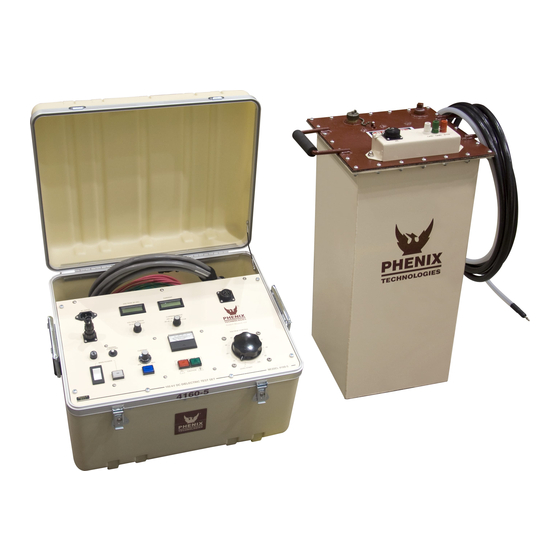
- Page 1 USER’S MANUAL DC DIELECTRIC TEST SET - 400P MODEL NUMBER 4160-5 Version 2.1 Phenix Technologies Inc. 75 Speicher Drive Accident, Maryland 21520 Copyright © Phenix Technologies, Inc Rev 5/28/2015 DCD 4160-5...
- Page 2 INTRODUCTION The DC HiPot line offered by Phenix Technologies is ruggedly built and suitable for field or lab use. Designed to test electrical switchgear, cables, motors, generators and protective equipment, the DC test set is popular because the equipment is more compact and lighter in weight than comparable AC equipment.
-
Page 3: Table Of Contents
INTRODUCTION DANGER / GENERAL SAFETY PRECAUTIONS TECHNICAL SPECIFICATIONS CONTROLS AND INDICATORS ELECTRICAL SET-UP OPERATING INSTRUCTIONS RETURN-GROUND-GUARD CONNECTIONS CALIBRATION TROUBLESHOOTING STORAGE OF EQUIPMENT CIRCUIT DIAGRAM SYMBOLS RECOMMENDED SPARE PARTS AND PARTS LIST PARTS ORDERING INFORMATION RETURNED MATERIAL ELECTRICAL DIAGRAMS DCD 4160-5... -
Page 4: Danger General Safety Precautions
DO NOT operate damaged equipment. Remove power, and do not use the equipment until safe operation can be verified by service-trained personnel. Phenix Technologies, Inc. assumes no liability for unsafe or improper use of test equipment. DCD 4160-5... -
Page 5: Technical Specifications
HV Unit: 18" W x 12.75" D x 27.75" H; 150 lbs. (457 mm W x 324 mm D x 705 mm H; 68 kg) Cables: 10 lbs. (4.5kg) *For 220 V units: add 10 lbs. (4.5 kg) DCD 4160-5... -
Page 6: Controls And Indicators
Circuit also acts as short circuit and overload protection on high voltage output. To reactivate high voltage, Voltage Control must be returned to zero, and Reset switch must be pressed to clear Current Trip circuit. DCD 4160-5... - Page 7 Some examples include footswitch, dead man switch, gate interlock, panic button, etc. Only non-energized contact devices may be used. This is a series 120 VAC circuit that must be maintained closed for high voltage to be activated, or maintained. DCD 4160-5...
- Page 8 CONTROLS AND INDICATORS FIGURE 2-1 DCD 4160-5...
- Page 9 Return (RTN) post or the Guard (GRD) post. Do not operate the unit with the clip removed or disconnected. High Voltage Bushing Well. High voltage output cable connects here. Opposite end attaches to the high potential side of the test specimen. DCD 4160-5...
- Page 10 CONTROLS AND INDICATORS FIGURE 2-2 DCD 4160-5...
-
Page 11: Electrical Set-Up
Improper contact with the test leads on this equipment can cause harmful or fatal electrical shock. Do not touch test leads while a test is in process. This equipment should only be operated by someone familiar with high voltage testing and safety procedures. DCD 4160-5... -
Page 12: Operating Instructions
After all testing is completed; turn off the front panel Main Power switch. Remove the input power cable from the facility power input. CAUTION: Make certain that the test specimen is totally discharged and grounded before removing test cables. DCD 4160-5... - Page 13 Example: 50 uA/1,000=0.05mA. The result can now be used directly in the above formula. 10kV divided by .05mA equals 200Meg-Ohms An alternate method is to use the formula; Kilovolts divided by Microamps multiplied by 1,000 equals Meg- Ohms. KV/uA x 1,000=Meg-Ohms Example: 10kV divided by 50uA times 1,000 equals 200Meg-Ohms DCD 4160-5...
-
Page 14: Return-Ground-Guard Connections
NOTE: Do not operate unit with the ground jumper removed or not connected to either Return or Guard. Make sure the Ground post is connected to a good earth ground. See connection diagrams on next pages (Figures 5-1 and 5-2). DCD 4160-5... - Page 15 DANGER HIGH VOLTAGE DANGER HIGH VOLTAGE DCD 4160-5...
- Page 16 RETURN-GROUND-GUARD CONNECTIONS FIGURE 5-2 DCD 4160-5...
-
Page 17: Calibration
80% of range. Adjust the reading on the panel meter (M1) by means of potentiometer R1 to a corresponding reading. Check Linearity and calibration at various other main points of the range such as 20%, 40%, 60%, 100%. Repeat for High range, adjusting R2. DCD 4160-5... - Page 18 Adjust potentiometer R103 until the Overload lamp illuminates and high voltage is shut off. Repeat steps "b" through "g" as necessary until both settings are calibrated. 4. Range Overcurrent. R235 sets an overcurrent for the ranges and should be set to trip at approximately 112% of 2mA range. DCD 4160-5...
-
Page 19: Troubleshooting
If the controls do not operate properly after having been used according to the instructions, the following hints may help. Check main facility input power to the test set. Check indicating lamps. (Spare lamps are available through Phenix Technologies.) Check fuse-F1. Check all external plug connections on the test set. -
Page 20: Storage Of Equipment
1. The equipment should be covered and kept in a warm, dry environment (95% maximum humidity, 5 to 30 Celsius). 2. In no case should the test unit be stored outdoors (unless previously specified in the original purchase agreement). DCD 4160-5... -
Page 21: Circuit Diagram Symbols
Normally Closed Interrupteur Normalement Schrittshalter Maintained Switch Maintenu Ferme (Oeffner) Normally Closed Interrupteur Normalement Druckschalter Momentary Switch Ferme Momentanement (Oeffner) Normally Open Interrupteur Normalement Druckschalter Momentary Switch Ouvert Momentanement (Schliesser) Current Overload Dispositif De Sur UeberstromschutzEinheit Device Intensite DCD 4160-5... - Page 22 SECTION 10: RECOMMENDED SPARE PARTS / 4160-5 PARTS LIST Phenix Technologies recommends that the customer purchase and stock the following parts for normal maintenance of the unit. The recommended quantity should be sufficient to support the unit during normal operation.
- Page 23 10-2 4160-5 PARTS LIST ITEM DESCRIPTION PART NO. CONTROLS C1, 4 47uF 20V Capacitor 1096510 C2, 3 1 uF 50V Capacitor 1094051 C5, 6 .033 uF 630v Capacitor 1093300 CABLE-INTERCONNECT 25 FT. INTERCONNECT CABLE ASSY. 30160002 CASE HD POLY CASE...
- Page 24 10-3 4160-5 PARTS LIST PART NO. CONTROLS (cont) ITEM DESCRIPTION 4 PIN CABLE CONNECTOR 1151162 CABLE CLAMP 1151186 CONTACT PINS-MALE 1151176 VARIABLE TRANSFORMER 1890120 T2 (220V ONLY) STEP DOWN AUTO TRANSFORMER 1894433 Z1-4 1.5KE18A TRANSORB 1780065 1.5KE18C TRANSORB 1780069 ITEM DESCRIPTION PART NO.
- Page 25 10-4 4160-5 PARTS LIST DCD 4160-5...
-
Page 26: Parts Ordering Information
When your purchase order is received at our office, a representative of Phenix Technologies will contact you to confirm the current price of the part being ordered. If a part you order has been replaced with a new or improved part, an Applications Engineer will contact you concerning any change in part number. -
Page 27: Returned Material
Serial Number Reason for Return Cause of Defect If Phenix Technologies, Inc. deems return of the part appropriate, it will then issue an "Authorization for Return." If return is not deemed advisable, other inspection arrangements will be made. NOTE: Material received at this plant without the proper authorization shall be held as "Customer's Property"... -
Page 28: Electrical Diagrams
13-1 SECTION 13: ELECTRICAL DIAGRAMS Drawing Number Description 1. 9400162 Model Number 4160-5 Electrical Schematic 2. 8430162 High Voltage Tank Assembly—4160-5 DCD 4160-5...
Need help?
Do you have a question about the 4160-5 and is the answer not in the manual?
Questions and answers